Method for compensating for flow rate of hydraulic pump of construction machine

a technology of hydraulic pump and flow rate, which is applied in the direction of servomotors, soil shifting machines/dredgers, fluid-pressure actuators, etc., can solve the problems of deteriorating fast operation speed of working devices, etc., and achieves the effect of improving operation sensibility and workability

Active Publication Date: 2019-02-19
VOLVO CONSTR EQUIP AB
View PDF7 Cites 3 Cited by
  • Summary
  • Abstract
  • Description
  • Claims
  • Application Information

AI Technical Summary

Benefits of technology

[0021]According to the embodier rent of the present invention having the above-described configuration, a dead zone of the discharge flow rate is avoided in the operation of the operation lever for driving the working device such as excavator, allowing the discharge flow rate to be controlled at the operator's intention and thus improving the operation sensibility and the workability.

Problems solved by technology

Thus, due to the existence of the dead zone in the operation of the operation lever, the discharge flow rate increases against the operator's intention, making the operation speed of the working device fast and deteriorating the operation sensibility and the workability.

Method used


Image

  • Method for compensating for flow rate of hydraulic pump of construction machine
  • Method for compensating for flow rate of hydraulic pump of construction machine
  • Method for compensating for flow rate of hydraulic pump of construction machine

Examples


Embodiment Construction

[0038]Hereinafter, a method for compensating a discharge flow rate of a hydraulic pump for construction equipment according to a preferred embodiment, of the present invention will be described in detail with reference to the accompanying drawings.

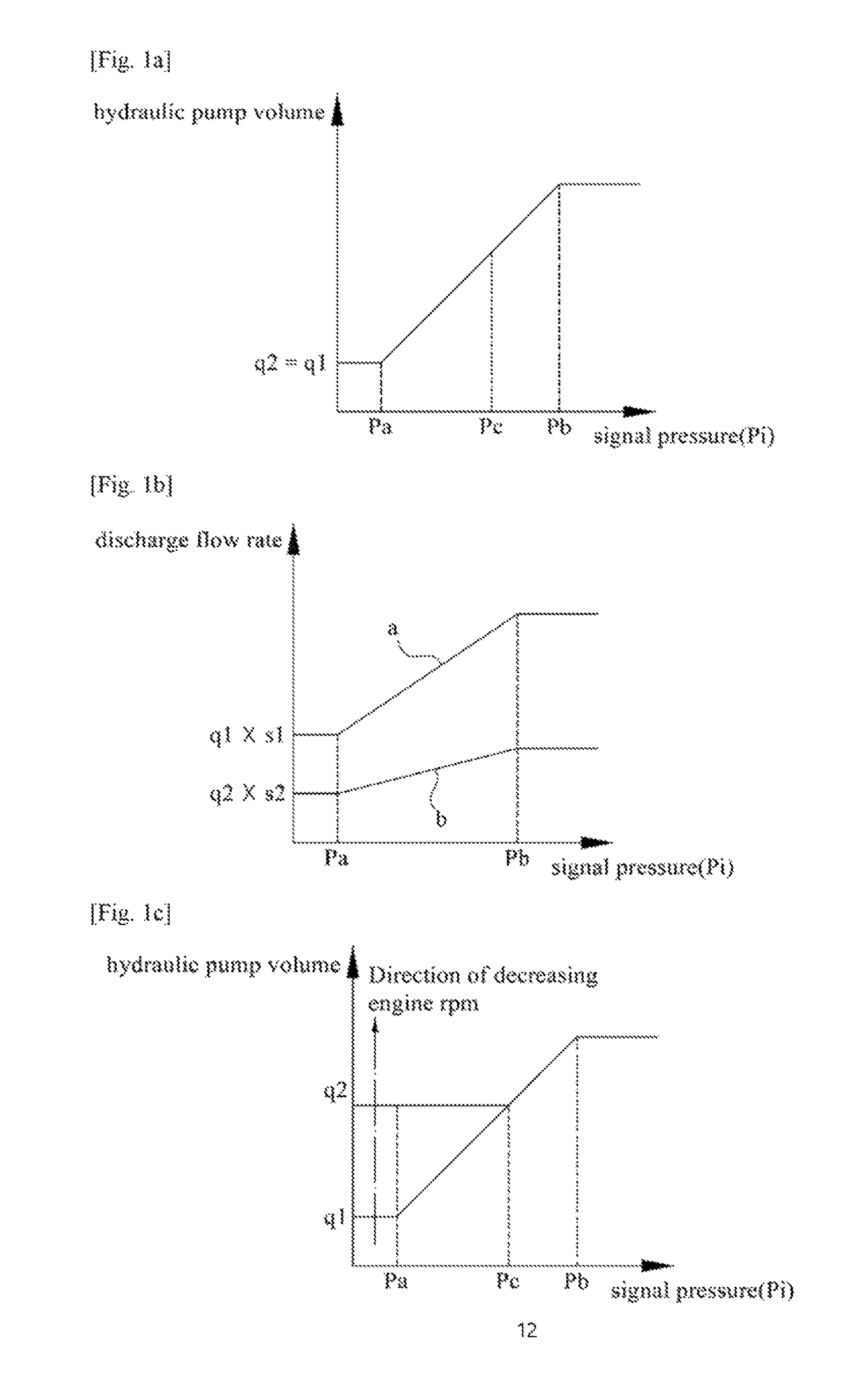
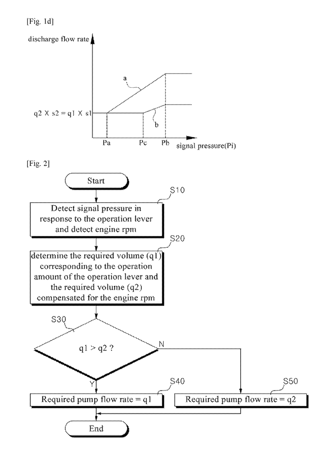
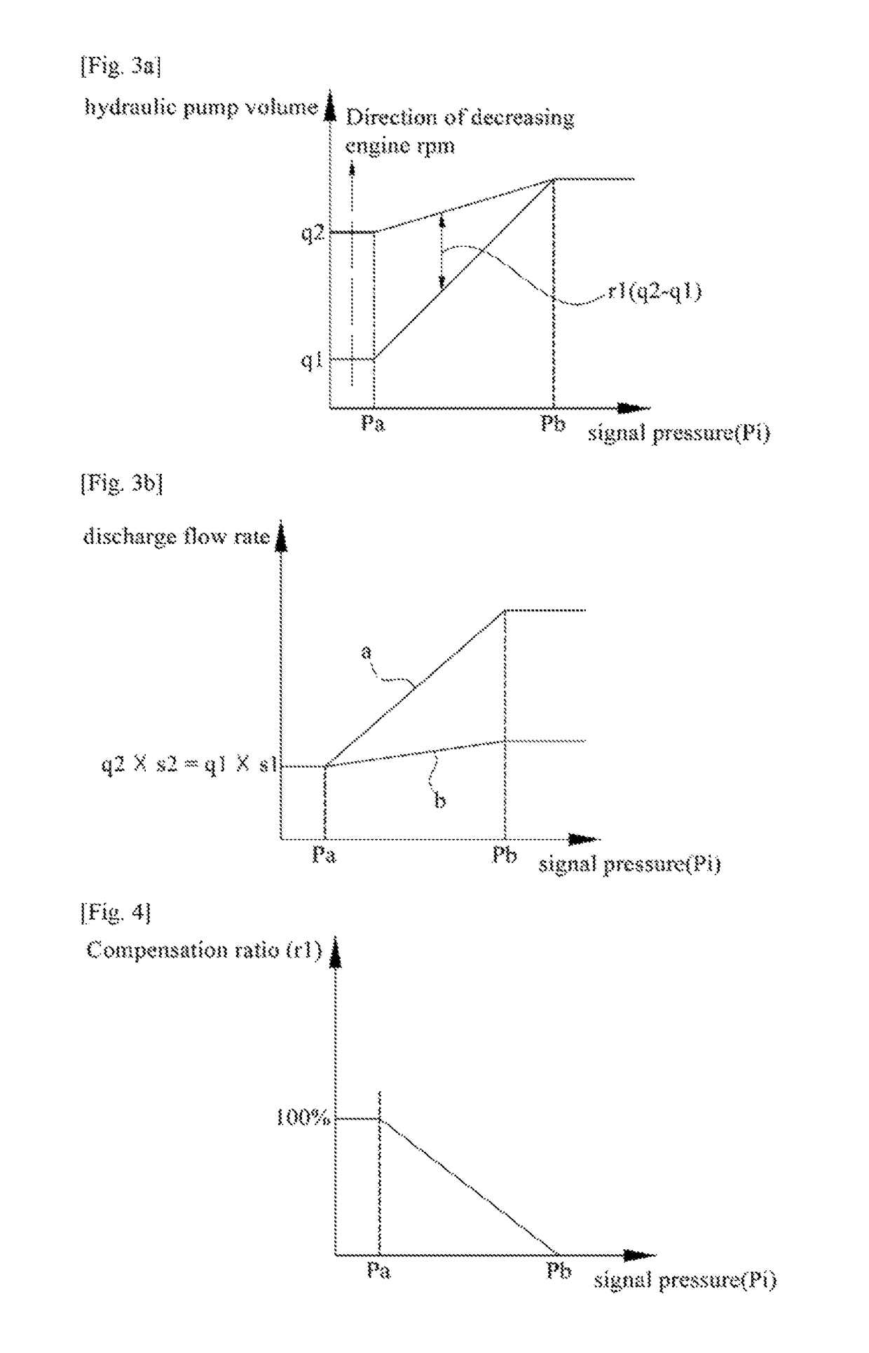
[0039]FIG. 3(a, b) are the graphs showing a pump volume and a discharge flow rate in response to an operation amount of the operation lever according to the embodiment of the present invention. FIG. 4 is the graph showing the functional relation between a volume compensation ratio and a pilot pressure by the operation of the operation lever in the method for compensating the discharge flow rate of the hydraulic pump according to the embodiment of the present invention. FIG. 5 is the flow chart showing the method for compensating the discharge flow rate of the hydraulic pump according to the embodiment of the present invention. FIG. 6 is the hydraulic circuit used for the method of compensating the discharge flow rate of the hydraulic pump ...


PUM


Abstract

A method is provided for compensating for the flow rate of a variable capacity-type hydraulic pump such that, when a manipulation lever is manipulated, a discontinuous section, which has no change in the discharge flow rate of the hydraulic pump, is eliminated.

Description

BACKGROUND AND SUMMARY[0001]The present invention relates to a method for compensating flow rate of hydraulic pump and more particularly, a method for compensating a discharge flow rate of hydraulic pump for construction machine in order to remove a dead zone in which the discharge flow rate does not change by operation of an operation lever.[0002]FIG. 1(a, b) are the graphs showing a pump volume and a discharge flow rate of a hydraulic pump in response to an operation amount of an operation lever according to the conventional technology, respectively,[0003]FIG. 1(a)shows that a pump volume of the hydraulic pump in response to a pilot pressure (Pi) applied to the control valve by operation of the operation lever does not vary depending on an engine RPM (Revolutions Per Minute).[0004]As shown in FIG. 1(b), a discharge flow rate (q1×s1) corresponding to a required pump volume (q1) in accordance with an operation amount of the operation lever, and a preset higher engine RPM (s1) repres...

Claims


Application Information

Patent Timeline
Patent Type & Authority Patents(United States)
IPC IPC(8): F15B11/05E02F9/22E02F9/20F15B13/042
CPCE02F9/2235E02F9/20E02F9/22E02F9/2285E02F9/2296F15B11/055F15B13/042F15B2211/857E02F9/2004E02F9/2267E02F9/2271F15B2211/523F15B2211/575E02F9/2282F15B11/0423F15B2211/20523F15B2211/20546F15B2211/633F15B2211/6346F15B2211/6652F15B2211/6654F15B2211/851
Inventor SHIN, HUNG-JULEE, SANG-HEE
Owner VOLVO CONSTR EQUIP AB
Why Eureka
Try Eureka