Eureka AIR delivers breakthrough ideas for toughest innovation challenges, trusted by R&D personnel around the world.

Progressive Non-Through Hole Glass Screen Protector and Manufacturing Method Thereof

a technology of glass screen protector and through-hole hole, which is applied in the field of glass screen protector, can solve the problems of affecting the sensing of the operation of a portable device, the thickness of the glass screen protector affects the sensing of the special sensing element such as the fingerprint reader, and the whole adhesive becomes too thin, so as to enhance the sensing area of the fingerprint elemen

Inactive Publication Date: 2021-03-04
J TING CO LTD
View PDF0 Cites 3 Cited by
  • Summary
  • Abstract
  • Description
  • Claims
  • Application Information

AI Technical Summary

Benefits of technology

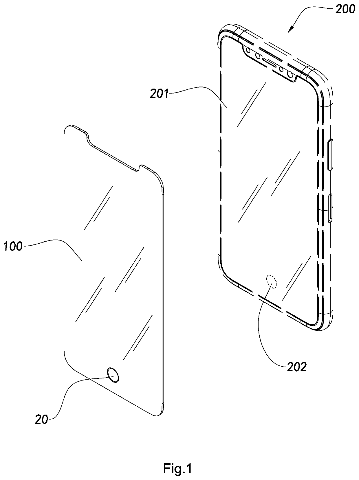
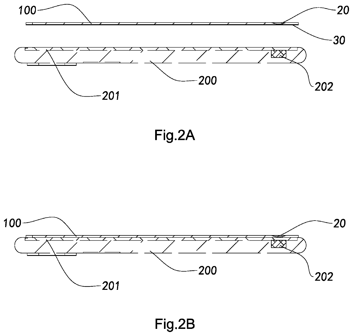
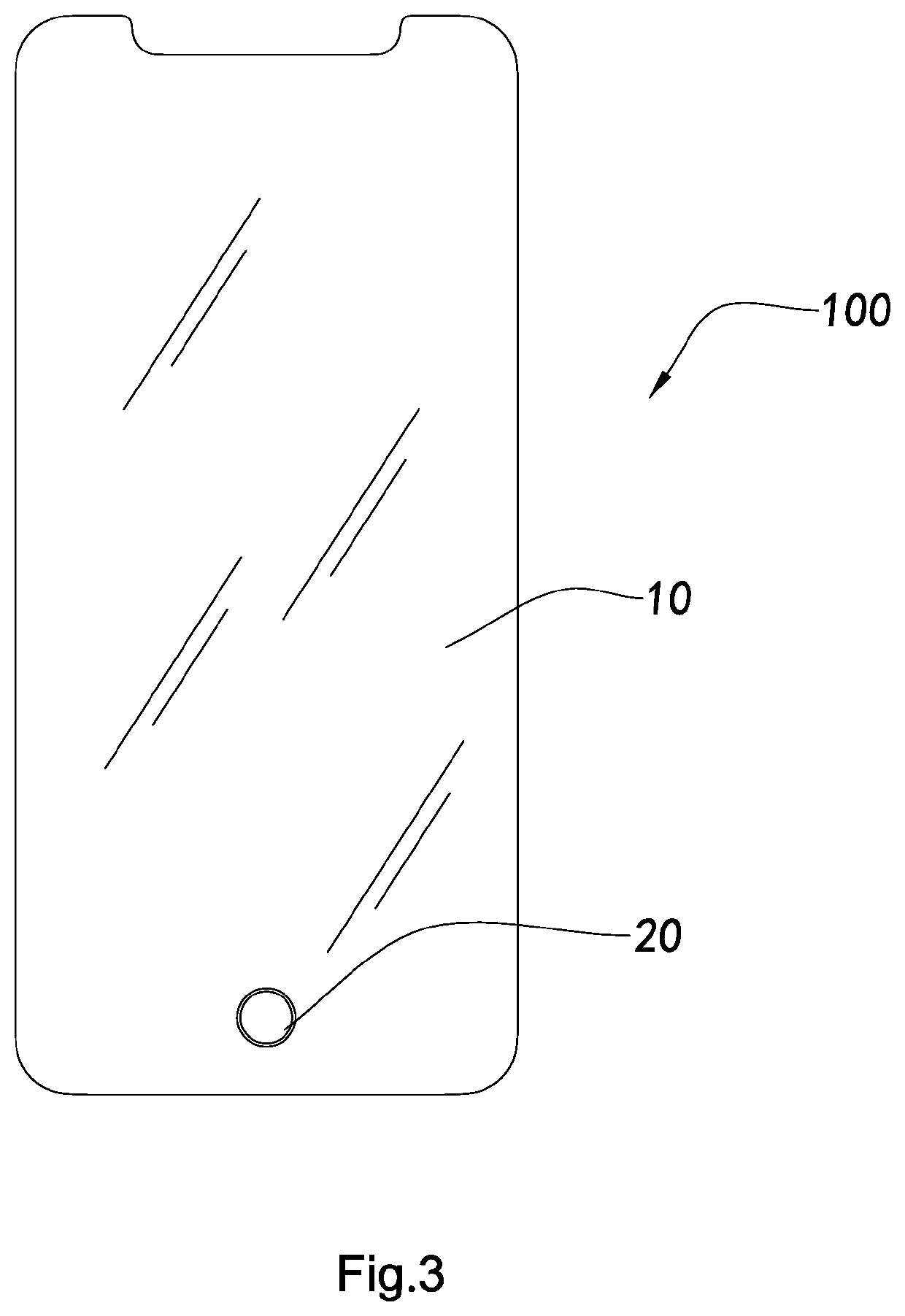
The present invention provides a progressive non-through hole glass screen protector for portable mobile electronic devices that has a part of thinner glass and no through hole, which enhances the sensibility of fingerprint elements and other electronic sensing elements. The glass screen protector has no offset or mismatch at the position of the fingerprint reader or electronic sensing element, giving a premium, smooth, and hole-free look and feel when touching the fingerprint position. The glass screen protector only partially reduces the thickness of the glass under a hole-free condition, so as not to impact the sensibility of the electronic sensing element of the device.

Problems solved by technology

One of the most common issues for conventional glass screen protectors is that the thickness of the glass screen protector affects the sensibility of the operation of a portable mobile electronic device when the glass screen protector is attached on the portable mobile electronic device.
Unfortunately, it will render the sensibility special sensing element, such as the fingerprint reader, fail or perform poorly.
Accordingly, there have been solutions for the prior arts, but there are some other drawbacks in these solutions as well.
Unfortunately, it causes a drawback that the whole adhesive becomes too thin, rendering uneven thickness of the adhesive when the backing device clamped.
As a result, bubbles or gum streaks are likely to occur when the glass screen protector is attached on the display of the portable mobile electronic device, which will impact the attachment and compactness between the glass screen protector and the display as well as cause poor appearance.
Nonetheless, this will prevent the thickness of the glass from being further reduced, which still fails to maintain a stable sensibility of the special sensing element, such as the fingerprint reader.
Nevertheless, this will have the glass screen protector directly contact the display and therefore, possibly scratch the display as well as render Newton's ring and poor appearance.
However, such practice will not only impact the wholeness as well as the appearance of the glass screen protector, but also render other drawbacks, including dust accumulation, head scratch risk, poor texture, and hole look of the display.
Similarly, this type of arrangement can affect the wholeness and beauty of the glass screen protector and is likely to render dust accumulation.
It is easy to understand that such arrangement will lower the overall strength and the fringe strength of the glass screen protector.
The user may crack the glass screen protector only by a gentle bump.
Therefore, it can barely protect the portable mobile electronic device effectively.
Similarly, this means cannot provide effective protection to the portable mobile electronic device, such as a cellphone.
When the device is dropped, it cannot protect the plate of the display from cracking.
That is to say, they somehow improve the utilization of the fingerprint reader, but create some other new problems as well.

Method used


Image

  • Progressive Non-Through Hole Glass Screen Protector and Manufacturing Method Thereof
  • Progressive Non-Through Hole Glass Screen Protector and Manufacturing Method Thereof
  • Progressive Non-Through Hole Glass Screen Protector and Manufacturing Method Thereof

Examples


Embodiment Construction

[0065]The following description is disclosed to enable any person skilled in the art to make and use the present invention. Preferred embodiments are provided in the following description only as examples and modifications will be apparent to those skilled in the art. The general principles defined in the following description would be applied to other embodiments, alternatives, modifications, equivalents, and applications without departing from the spirit and scope of the present invention.

[0066]Those skilled in the art should understand that, in the disclosure of the present invention, terminologies of “longitudinal,”“lateral,”“upper,”“front,”“back,”“left,”“right,”“perpendicular,”“horizontal,”“top,”“bottom,”“inner,”“outer,” and etc. just indicate relations of direction or position are based on the relations of direction or position shown in the appended drawings, which is only to facilitate descriptions of the present invention and to simplify the descriptions, rather than to indi...


PUM

PropertyMeasurementUnit
thicknessaaaaaaaaaa
thicknessaaaaaaaaaa
sizeaaaaaaaaaa

Abstract

A glass screen protector manufacturing method of a progressive non-through hole glass screen protector includes the steps of cutting a glass screen protector pattern; CNC machining the glass screen protector for a side edge, a progressive sensing area, and a desired hole position thereof; polishing the glass screen protector; reinforcing the glass screen protector; coating the glass screen protector with a nano coating; and gluing a backing to the glass screen protector.

Description

NOTICE OF COPYRIGHT[0001]A portion of the disclosure of this patent document contains material which is subject to copyright protection. The copyright owner has no objection to any reproduction by anyone of the patent disclosure, as it appears in the United States Patent and Trademark Office patent files or records, but otherwise reserves all copyright rights whatsoever.BACKGROUND OF THE PRESENT INVENTIONField of Invention[0002]The present invention relates to the field of glass screen protector, and, in particular, to a progressive non-through hole glass screen protector and manufacturing method thereof, wherein when the glass screen protector is applied on a portable mobile electronic device, the glass screen protector is capable of increasing the sensibility of the fingerprint reader or sensing element without having a through hole or impact to the appearance.Description of Related Arts[0003]As science and technology advance by leaps and bounds, it produces a golden age of the de...

Claims


Application Information

Patent Timeline
Patent Type & Authority Applications(United States)
IPC IPC(8): B32B37/18C03C19/00C03C17/00C03B19/09B32B7/12B32B3/26B32B17/06B32B37/12B32B38/00C03C21/00B24B7/24
CPCB32B37/18B32B2457/202C03C17/002C03B19/09B32B7/12B32B3/263B32B17/06B32B37/12B32B38/0004B32B38/0012C03C21/002B24B7/24B32B2038/0064B32B2255/00B32B2305/08B32B2307/558B32B2315/08C03C19/00B24B1/00C03B33/02C03C17/00C03C2217/70C09J2400/143C09J7/20H04M1/185
Inventor KUO, HSIN-HUNG
Owner J TING CO LTD
Why Eureka
Eureka Blog
Learn More