Multi-directional optical receiver and method

a multi-directional optical receiver and receiver technology, applied in the field of multi-directional optical receivers and methods, can solve the problems of increasing the size, weight, power and cost of the system, requiring complex optics, and most multi-directional collection systems being impractical for small platforms, so as to improve the efficiency of multi-directional collection systems, reduce power consumption, and simplify the effect of active optical systems

Active Publication Date: 2019-02-19
RAYTHEON CO
View PDF41 Cites 10 Cited by
  • Summary
  • Abstract
  • Description
  • Claims
  • Application Information

AI Technical Summary

Benefits of technology

[0002]Aspects and embodiments are generally directed to optical systems and methods, and in particular, to multi-directional optical receivers and methods of using the same. Aspects and embodiments include solid-state active components and / or non-mechanical optical elements for improved weight reduction and reduced power consumption during such conditions. One example of an optical receiver includes a plurality of fused fiber optic bundles coupled to a single photo-detector, and positioned to directly collect optical radiation from a scene. In particular, a field of view of each of the fused fiber optic bundles collectively defines an omnidirectional field of view of the photo-detector. In various other arrangements, a field of view of each of the fused fiber optic bundles collectively defines a distributed aperture of the optical receiver. Accordingly, in addition to allowing a more simplified active optical system when compared to typical multi-directional optical receivers, various aspects and embodiments provide a reduced weight, size, and power consumption optical receiver for ground, mobile, maritime, airborne, and space applications.

Problems solved by technology

However, these systems traditionally require complex optics to provide a line-of-sight between the collection apertures and the numerous photo-detectors.
The complex optics can increase the size, weight, power, and cost of the system, and make most multi-directional collection systems impractical for small platforms.

Method used


Image

  • Multi-directional optical receiver and method
  • Multi-directional optical receiver and method
  • Multi-directional optical receiver and method

Examples


Embodiment Construction

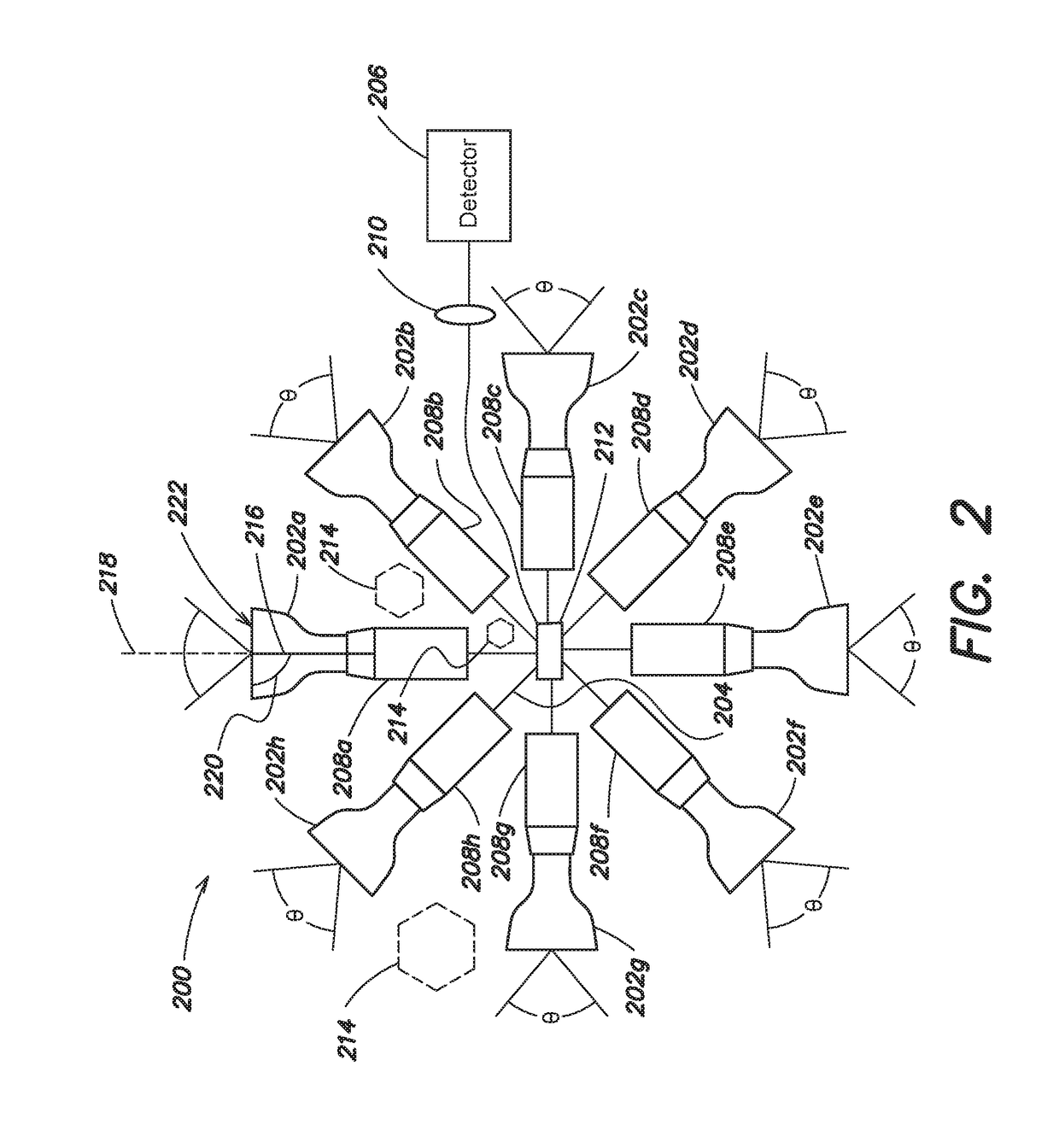
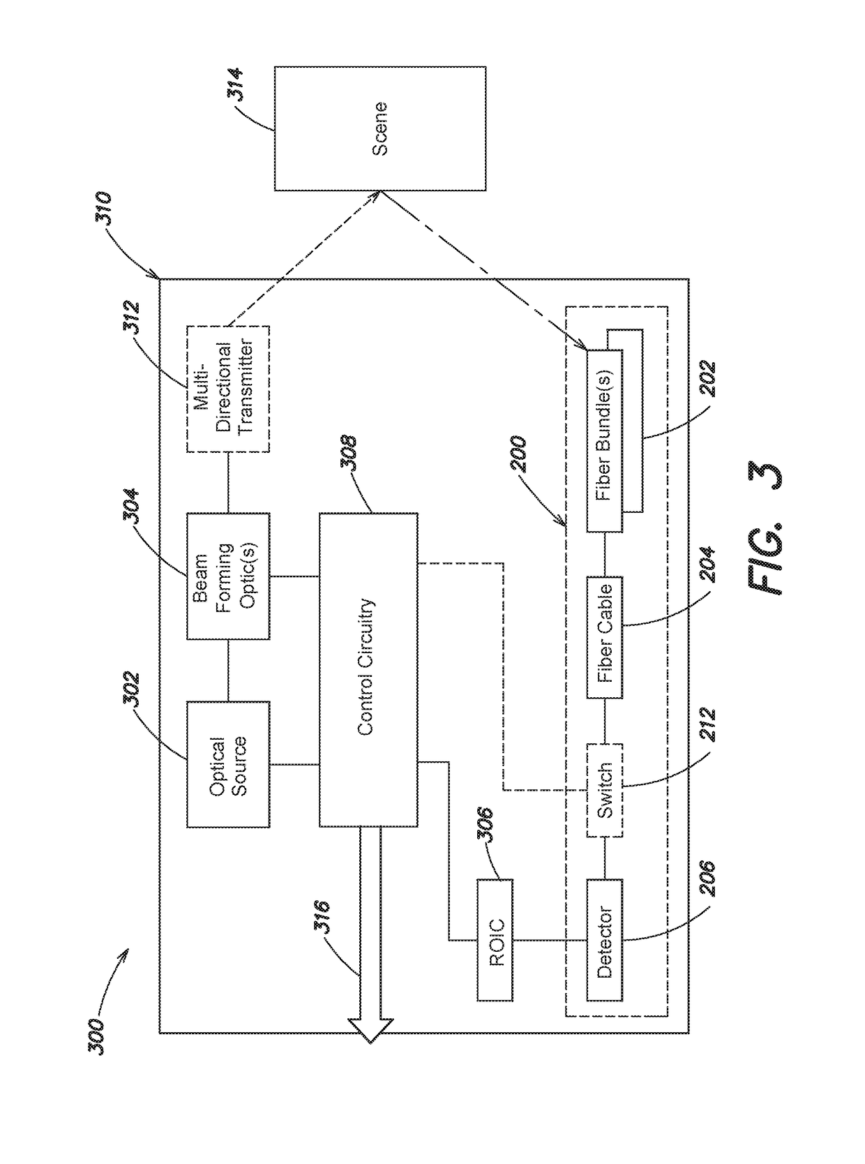
[0019]Aspects and embodiments are generally directed to optical systems and methods, and in particular, to optical receivers having a multi-directional field of view, and methods of using the same. One example of an optical receiver includes a plurality of fused fiber optic bundles positioned to directly collect optical radiation from a scene, and direct that optical radiation to a single pixelated or non-pixelated photo-detector. In particular, a field of view of each of the fused fiber optic bundles collectively defines a multi-directional (e.g., omnidirectional) field of view of the photo-detector. In addition to allowing a more simplified active optical system, various aspects and embodiments provide a reduced weight, size, and power consumption optical receiver for ground, mobile, maritime, airborne, and space applications. Particularly, the photo-detector may include a reduced size photo-detector having a single linear array of unit cells, or a single unit cell. Such aspects a...


PUM


Abstract

Aspects and embodiments are generally directed to optical systems, receivers, and methods. In one example, an optical receiver includes a plurality of fused fiber optic bundles, at least a first fused fiber optic bundle of the plurality of fused fiber optic bundles positioned to collect optical radiation from a scene, a multi-mode fiber optic cable coupled to each fused fiber optic bundle of the plurality of fused fiber optic bundles, the multi-mode fiber optic cable configured to propagate the collected optical radiation from each of the plurality of fused fiber optic bundles along a length of the multi-mode fiber optic cable, and a photo-detector coupled to the multi-mode fiber optic cable and configured to receive the collected optical radiation. A field of view of each fused fiber optic bundle of the plurality of fused fiber optic bundles may collectively define a substantially omnidirectional field of view of the photo-detector.

Description

BACKGROUND[0001]Optical remote sensing systems and devices are used in numerous military and commercial applications. Various optical systems demand multi-directional radiation collection over a large field of view for effective operation. For instance, many optical systems, such as those employed in collision avoidance systems for unmanned vehicles, include numerous photo-detectors and associated optics arranged to collectively receive radiation over the desired angular range. However, these systems traditionally require complex optics to provide a line-of-sight between the collection apertures and the numerous photo-detectors. The complex optics can increase the size, weight, power, and cost of the system, and make most multi-directional collection systems impractical for small platforms.SUMMARY OF THE INVENTION[0002]Aspects and embodiments are generally directed to optical systems and methods, and in particular, to multi-directional optical receivers and methods of using the same...

Claims


Application Information

Patent Timeline
Patent Type & Authority Patents(United States)
IPC IPC(8): G02B6/04H04N5/225G02B6/35G02B6/32G02B6/08H04N1/193H04N5/232G01S7/481
CPCG02B6/08G02B6/32G02B6/3544H04N5/2254H04N5/23238G01S7/4818H04N1/1936G02B6/06G02B6/26G02B6/42H04N23/55H04N23/698
Inventor KELLER, SEAN D.UYENO, GERALD P.
Owner RAYTHEON CO
Why Eureka
Try Eureka