Optical system for object detection and location

an optical system and object technology, applied in the field of optical systems for object detection and location, can solve the problems of increasing the required input power and the size of the active optical system, increasing the size, weight and power of the optical system, etc., to improve the efficiency of operation, improve the effect of weight reduction and improved size reduction

Active Publication Date: 2019-04-23
RAYTHEON CO
View PDF28 Cites 8 Cited by
  • Summary
  • Abstract
  • Description
  • Claims
  • Application Information

AI Technical Summary

Benefits of technology

[0003]Aspects and embodiments are generally directed to imaging systems and methods, and in particular to imaging systems and methods for detecting objects in low-visibility and other restricted view conditions. Aspects and embodiments include solid-state active components and / or non-mechanical optical elements for improved size reduction, improved weight reduction, and reduced power consumption during operation. One example of an imaging system includes a non-mechanical beamsteering device positioned to scan a pulsed laser beam in a linear scan over an area of a scene.
[0004]As discussed in further detail herein, reflections of the pulsed laser beam from the area of the scene, and reflections from multiple consecutive linear scans over different areas of the scene, may be used to identify the presence of an object within the scene, locate and determine a range to that object, detect a spatial profile of that object, and / or generate an image of that object. In particular examples, the imaging system may locate small objects at great ranges (or other difficult to detect objects) based on the reflective characteristics of the scene and small objects therein. In addition to those benefits discussed herein, various aspects and embodiments provide a reduced weight, size, and power consumption imaging system for ground, mobile, maritime, airborne, and space, imaging environments.

Problems solved by technology

Longer ranges and wider fields of view require high powered laser sources, which directly increase the required input power and the size of the active optical system.
Such components also increase the size, weight, and power of the optical system.

Method used


Image

  • Optical system for object detection and location
  • Optical system for object detection and location
  • Optical system for object detection and location

Examples


Embodiment Construction

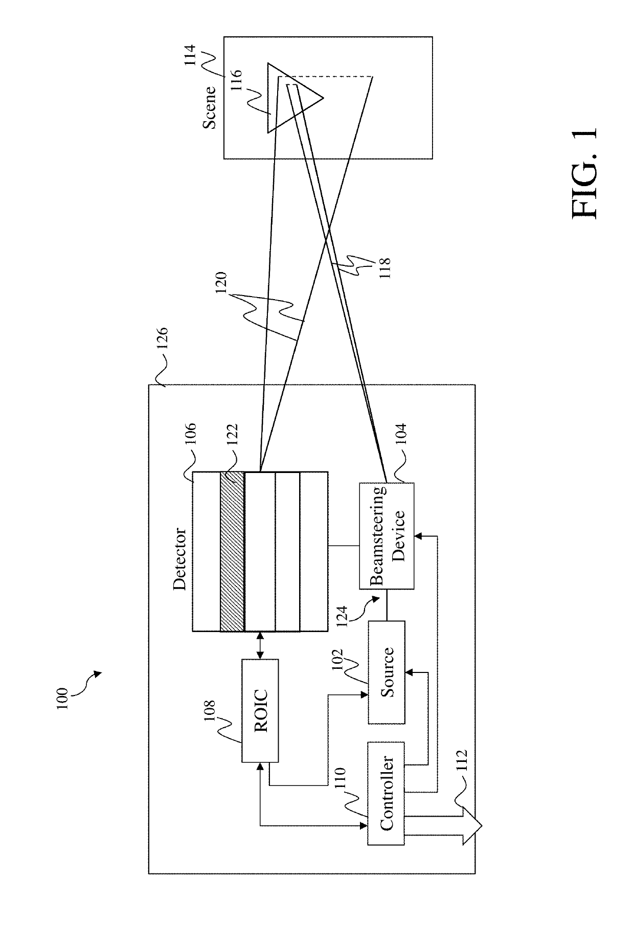
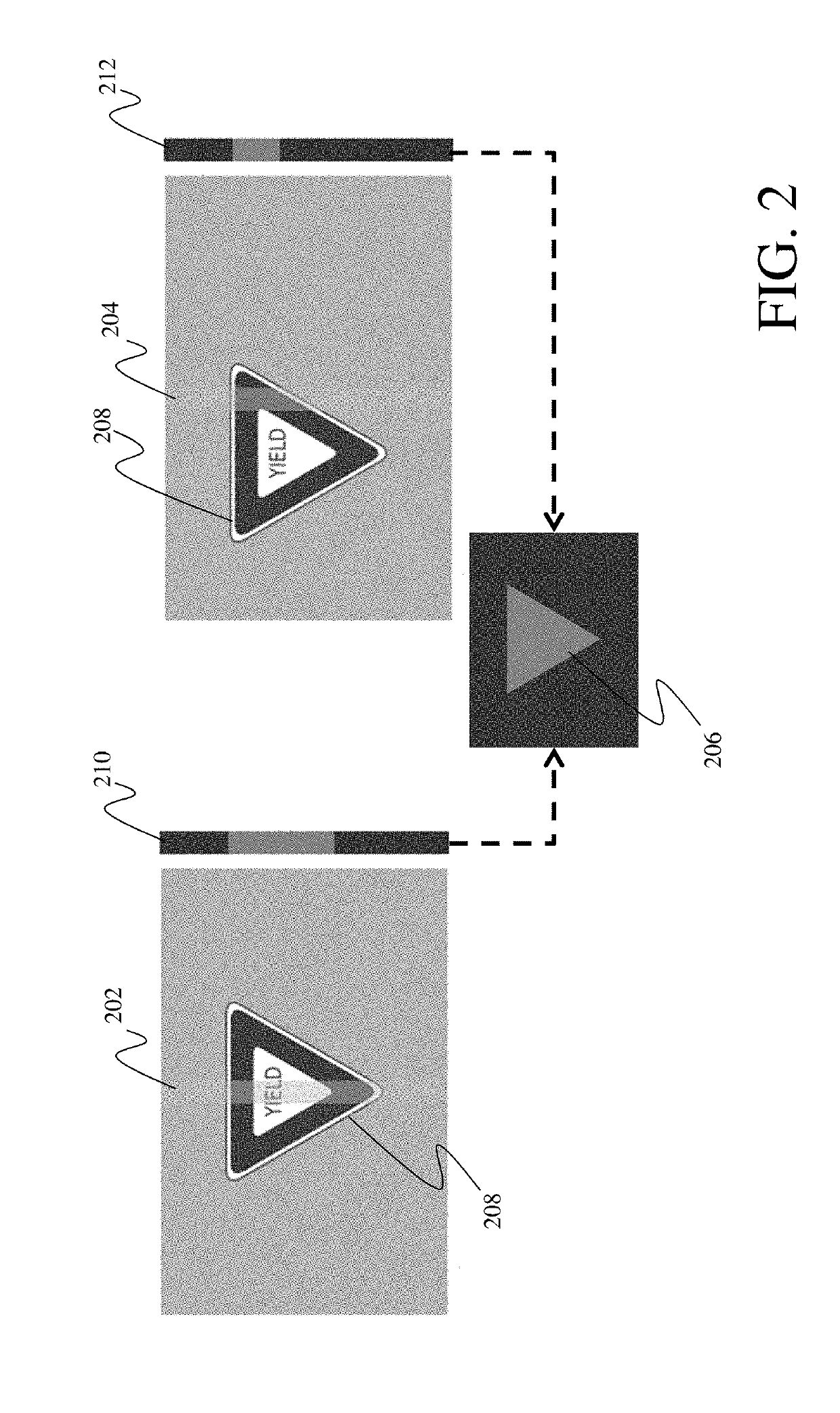
[0023]Aspects and embodiments relate to optical systems and methods of using the same. In particular, aspects and embodiments are directed to laser radar imaging systems and methods for detecting objects at long ranges, in low-visibility conditions, and in other restricted view conditions. Various embodiments include solid-state active components and / or non-mechanical optical elements for improved weight reduction and reduced power consumption during such conditions. As further discussed below, reflections of one or more scanned pulsed laser beams from an illuminated area of a scene may be used to identify the presence of an object in the scene, locate and determine an angular-range and distance (i.e., range) to the object, detect a spatial profile of the object, and generate an image of the object. In particular examples, the imaging system may locate small objects at great ranges (or other difficult to detect objects) based on a comparison of one or more signal levels correspondin...


PUM

PropertyMeasurementUnit
eye-safe wavelengthaaaaaaaaaa
wavelengthsaaaaaaaaaa
wavelengthaaaaaaaaaa

Abstract

Optical systems and methods for object detection and location. One example of an optical system includes a laser radar optical source positioned to emit a pulsed laser beam, a non-mechanical beamsteering device positioned to scan the beam in a linear scan over a first area of a scene, a laser radar detector positioned to receive and integrate a reflection of the beam, a read-out integrated circuit (ROIC) configured to provide a first read-out signal based on the integrated reflection, and a controller configured to receive the first read-out signal, determine a range to the first area based on a time of flight of the pulsed laser beam, and identify a presence of an object within the scene based on a signal level of the first read-out signal, the first signal level corresponding to a reflectivity of a portion of the object within the first area of the scene.

Description

BACKGROUND[0001]Typical active optical systems use laser radiation to detect and locate objects. Such systems detect an object by sensing reflections of laser radiation from the object. After the object has been detected, these systems locate the object by determining an angular location of the object and a range to the object. Conventional active optical systems illuminate an entire field of view of the system instantaneously with sufficient laser energy to detect even the lowest reflective objects within that field of view, and at a maximum desired range. A detector within the optical system includes a given number of pixels, each having a sufficient sensitivity to detect the reflected laser radiation from the entire field of view. The reflected laser radiation is analyzed to determine a distance (i.e., range) to the object. Typically, range is determined by direct detection (e.g., the “time of flight” principle), or by frequency modulation.[0002]The size, weight, and power of a t...

Claims


Application Information

Patent Timeline
Patent Type & Authority Patents(United States)
IPC IPC(8): G01S17/02G01S17/66G01S17/42G02F1/29G01S7/48G01S17/89G01S7/481G01S7/484G01S7/486G01S7/487G01S17/10
CPCG01S17/026G01S7/4802G01S7/484G01S7/4813G01S7/4817G01S7/4863G01S7/4865G01S17/10G01S17/42G01S17/89G02F1/292G01S7/4873G01S17/66G01S17/04
Inventor UYENO, GERALD P.KELLER, SEAN D.
Owner RAYTHEON CO
Why Eureka
Try Eureka