

Storage system which utilizes two kinds of memory devices as its cache memory and method of controlling the storage system
- Summary
- Abstract
- Description
- Claims
- Application Information
AI Technical Summary
Benefits of technology
Problems solved by technology
Method used
Image

Examples
first embodiment
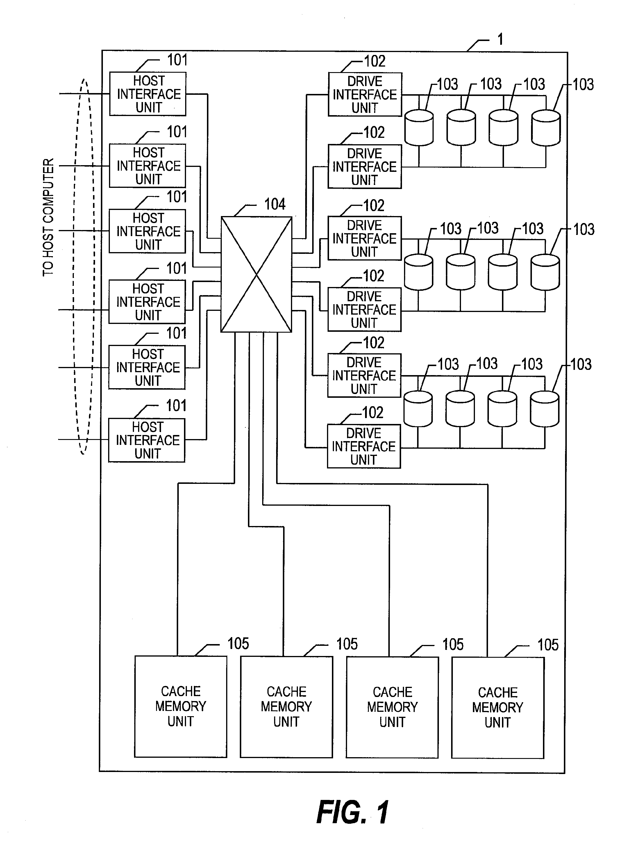
[0019]FIG. 1 is a block diagram showing an example of an overall configuration of a storage system 1 according to this invention.
[0020]As shown in FIG. 1, the storage system 1 includes at least one host interface unit 101, at least one drive interface unit 102, at least one disk drive 103, a transfer unit 104, and at least one cache memory unit 105.
[0021]The host interface unit 101 is coupled to a host computer(not shown), and communicates data with the host computer. The drive interface unit 102 is coupled to a plurality of disk drives 103, and controls the disk drives 103. The cache memory unit 105, according to a request received by the host interface unit 101 from the host computer, temporarily stores data read from the disk drive 103 and data to be written to the disk drive 103.
[0022]The transfer unit 104 couples between the host interface units 101 and the cache memory units 105, and between the drive interface units 102 and the cache memory units 105. In FIG. 1, the single tr...
second embodiment
[0093]A description will now be given of this invention.
[0094]FIG. 7 is a flowchart showing an example of a process performed upon a cache hit in the storage system 1 according to the second embodiment of this invention.
[0095]Specifically, the process of FIG. 7 is the second example of the process performed if it is determined that the requested data is present in the DRAM 211 in the step 303 of FIG. 3, and if it is determined that the requested data is present in the flash memory 212 in the step 305 of FIG. 3.
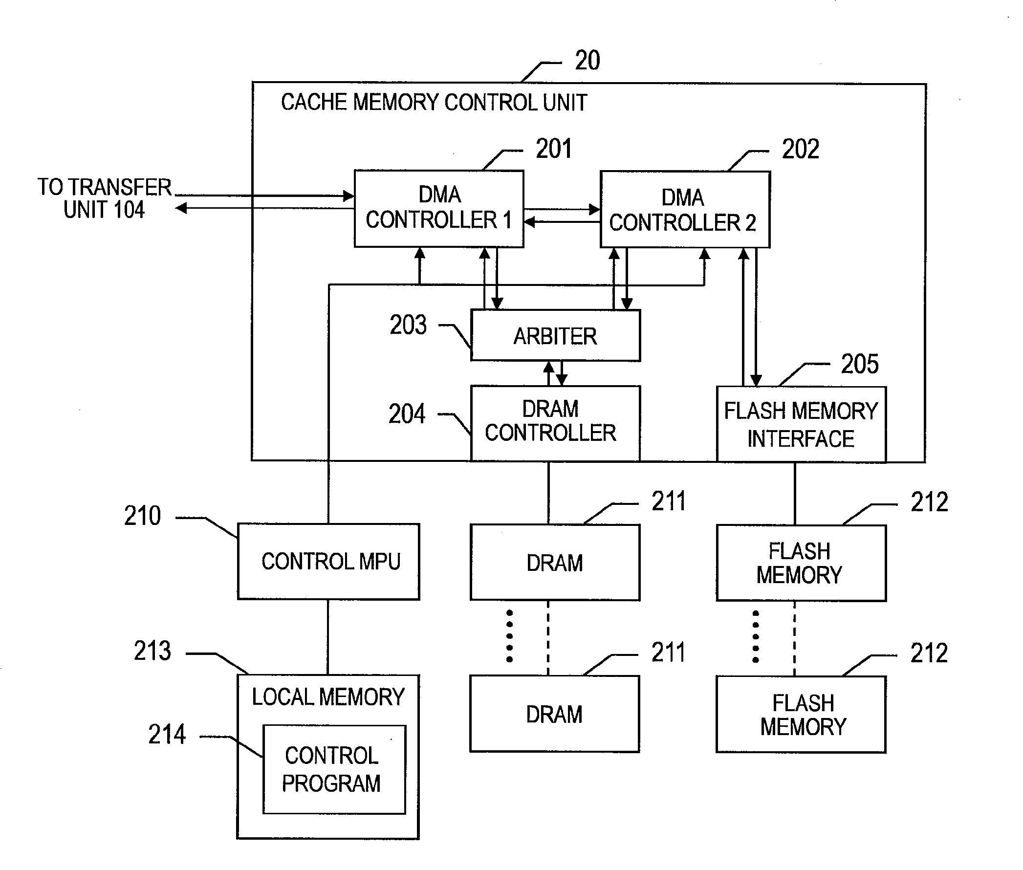
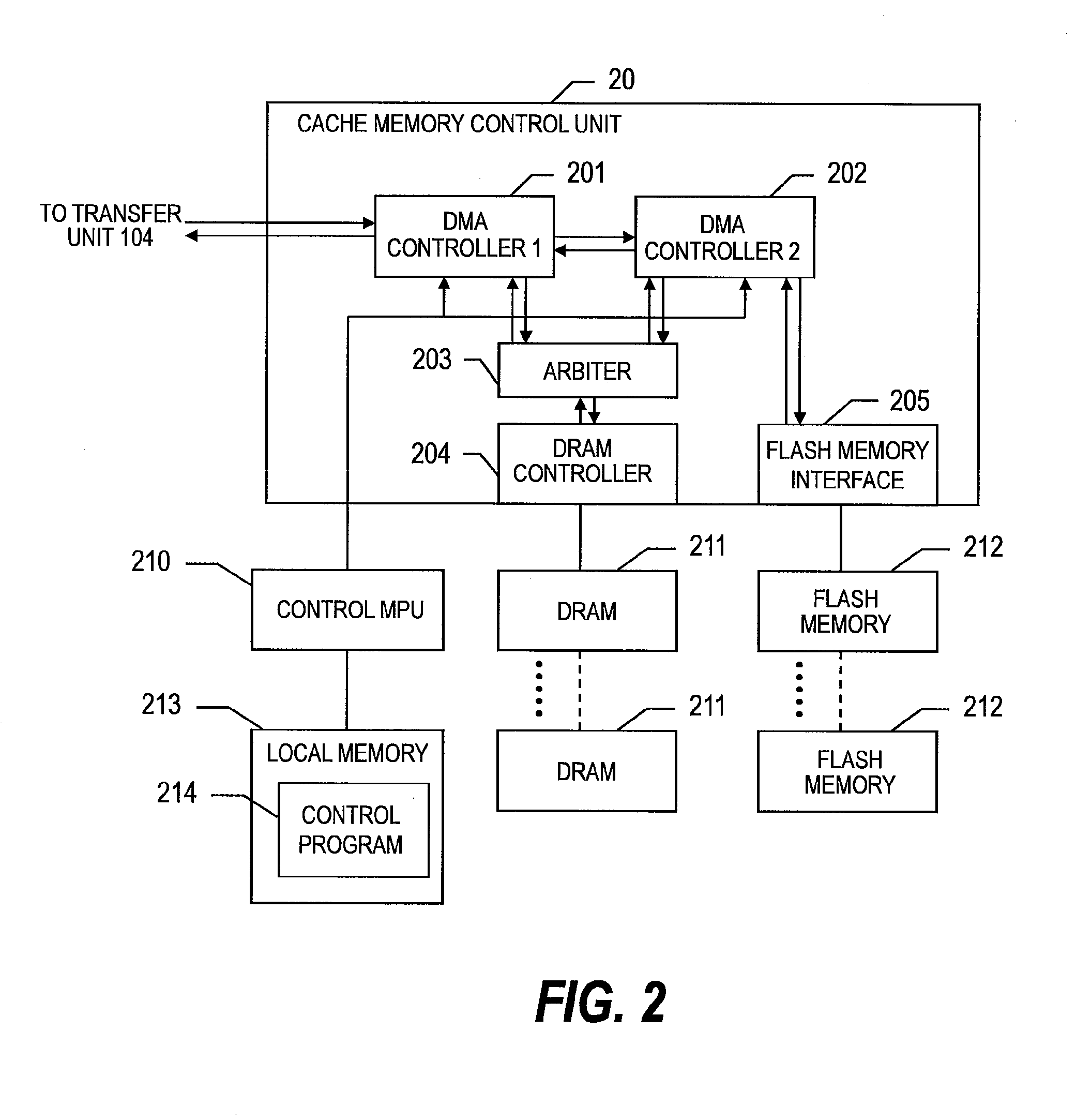
[0096]Configurations of the storage system 1 and the cache memory unit 105 of the second embodiment of this invention are the same as those of the first embodiment (see FIGS. 1 and 2). In the storage system 1 according to the second embodiment of this invention, except that a process shown in FIG. 7 is performed in place of the process shown in FIG. 4, the same process as that of the first embodiment of this invention is performed. Hereinafter, a description will be given of o...
third embodiment
[0109]A description will now be given of this invention.
[0110]Configurations of the storage system 1 and the cache memory unit 105 of the third embodiment of this invention are the same as those of the first embodiment of this invention (see FIGS. 1 and 2). In the storage system 1 according to the third embodiment of this invention, except that a process shown in FIG. 8 is performed in place of the process shown in FIG. 6, the in same process as that of the first embodiment of this invention is performed. Hereinafter, a description will be given of only cases of the third embodiment of this invention different from the first embodiment of this invention.
[0111]FIG. 8 is a flowchart showing an example of the DRAM free area collection process carried in the storage system 1 according to the third embodiment of this invention.
[0112]It should be noted that, according to the third embodiment of this invention, as the DRAM free area collection process in the step 306 of FIG. 3 and in the s...
PUM
 Abstract
Description
Claims
Application Information