Air filter arrangement

a filter arrangement and air filter technology, applied in the field of air filters, can solve the problems of increasing shipping costs, occupying significant storage space, and not allowing excessive bypass of unfiltered air flow, and achieve the effect of reducing the volume of air flow

Active Publication Date: 2019-02-26
ULTRAPLEAT LLC
View PDF22 Cites 1 Cited by
  • Summary
  • Abstract
  • Description
  • Claims
  • Application Information

AI Technical Summary

Benefits of technology

[0016]A lattice restraint panel is installed on one side of the frame occupying the frame opening to provide a restraint against excessive bulging of the expanded filter element when air is flowing through the same filter. A flange is interposed between the perimeter of the filter element and adjacent portions of the lattice restraint to prevent direct contact with the filter element and thereby minimize tearing of the filter element by direct contact with the lattice restraint.

Problems solved by technology

Such filters are designed to be disposable since they become dirty and clogged in a relatively short time and are not easily cleanable.
A significant disadvantage of such disposable air filters, is that their relative bulkiness increases the shipping costs and may occupy significant storage space if large numbers of filters are involved.
However, it is important that the filter be easily installed in the frame and would not allow excessive bypass of unfiltered air flow around the separate filter element.
Air filter elements are also typically made of porous paper or fiber and are somewhat vulnerable to being torn or otherwise damaged by incidental contact with the planar restraint, allowing unfiltered air to pass through the tears in the filter element.

Method used


Image

  • Air filter arrangement
  • Air filter arrangement
  • Air filter arrangement

Examples


Embodiment Construction

[0025]In the following detailed description, certain specific terminology will be employed for the sake of clarity and a particular embodiment described in accordance with the requirements of 35 USC 112, but it is to be understood that the same is not intended to be limiting and should not be so construed inasmuch as the invention is capable of taking many forms and variations within the scope of the appended claims.

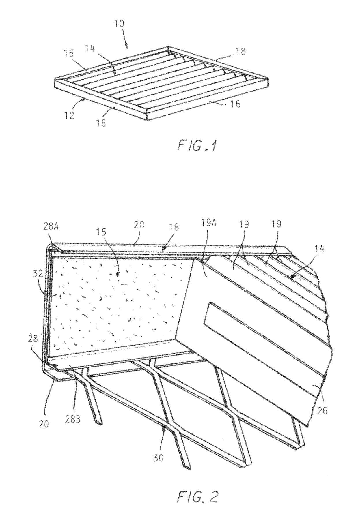
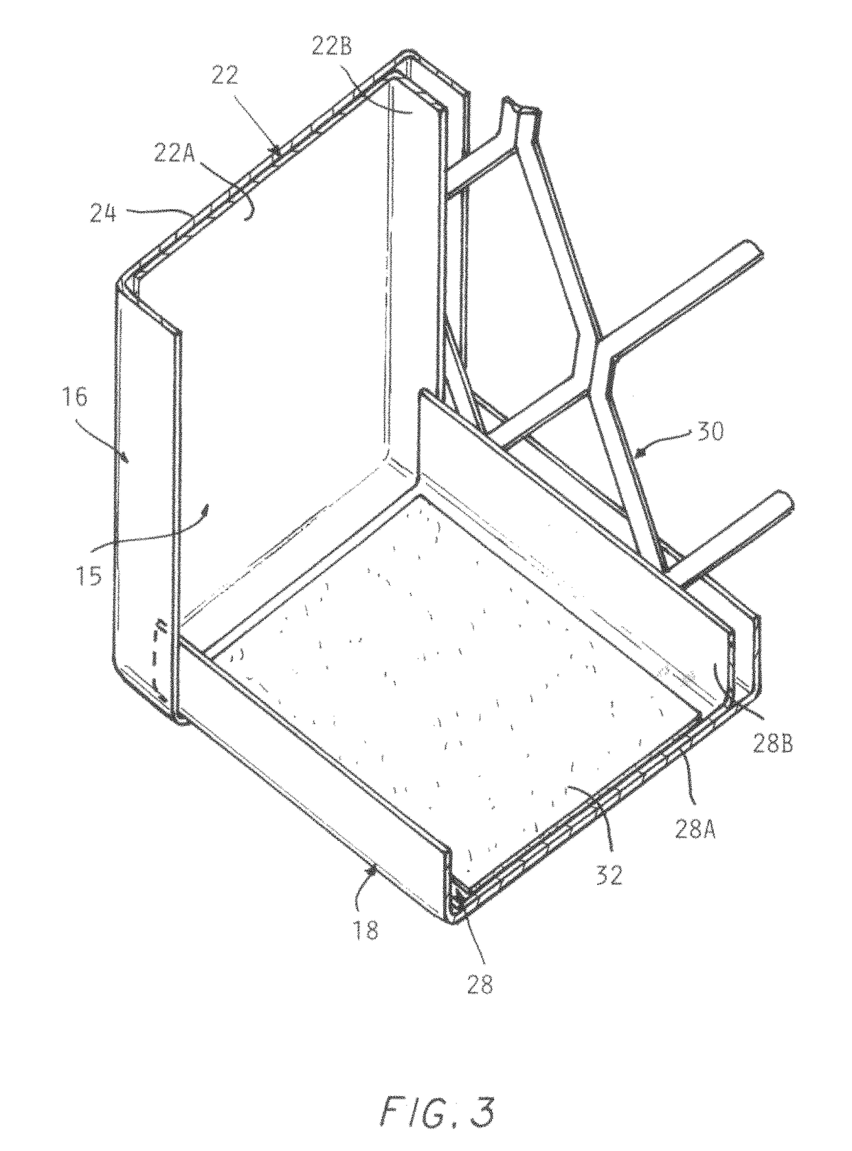
[0026]Referring to the drawings and particularly FIG. 1, the air filter arrangement 10 according to the invention is comprised of a rectangular formed steel open frame 12 and a pleated filter element 14 installed therein and formed from a porous fibrous sheet material. The frame 12 is made up of opposite pairs of sides 16, 18, each comprised of channels of a formed metal construction.

[0027]The pleated filter element 14 is collapsible into a stack of layers by folding the pleats 19 flat together, greatly reducing their volume for storage and shipping. The pleats 19 are sh...


PUM

PropertyMeasurementUnit
shapeaaaaaaaaaa
timeaaaaaaaaaa
forcesaaaaaaaaaa

Abstract

An air filter arrangement incorporates a replaceable pleated air filter element which is installed in a rectangular frame. The air filter element is collapsible by flattening together the pleats and placed in an opening in the frame and thereafter stretched apart to extend across the space opposite frame sides and held in that position, by a magnetic element on the end pleat at either end of the air filter element. Sealing pads made of a material similar to the filter element panels are secured to the other two opposite frame sides which engage respective opposite ends of the air filter element for reducing air flow around the pleat ends. A planar lattice restraint is held in a perimeter slot extending around the frame opening to prevent contact of the air filter element and the lattice restraint to minimize the risk of holes being torn in the filter element by such contact.

Description

BACKGROUND OF THE INVENTION[0001]This invention concerns air filters and more particularly disposable air filters of a type in common use with heating, air conditioning and ventilation (HVAC) systems.[0002]Such filters are designed to be disposable since they become dirty and clogged in a relatively short time and are not easily cleanable.[0003]The usual arrangement invoices generally planar fibrous air filter element fixed in a paperboard frame which supports the air filter element.[0004]The filter element and frame being integrally connected together are discarded as a unit.[0005]A significant disadvantage of such disposable air filters, is that their relative bulkiness increases the shipping costs and may occupy significant storage space if large numbers of filters are involved.[0006]For this reason, it would be advantageous if the filters could be made to be more compact for shipping and storage.[0007]One approach is to make the filter elements separable from the frame and to be...

Claims


Application Information

Patent Timeline
Patent Type & Authority Patents(United States)
IPC IPC(8): B01D46/00B01D46/10B01D46/52
CPCB01D46/0005B01D46/521B01D46/10
Inventor ELLIOTT, CORY
Owner ULTRAPLEAT LLC
Why Eureka
Try Eureka