Roll of paperband

a paper band and roll technology, applied in the field of paper band roll, can solve the problems that none of the above-described paper devices is satisfactory for use in the paper band track assembly beneath the wide paper machine, and achieve the effect of shortening the length of the paper band and minimizing the tearing of the paper band

Inactive Publication Date: 2006-12-07
SANDAR IND
View PDF6 Cites 8 Cited by
  • Summary
  • Abstract
  • Description
  • Claims
  • Application Information

AI Technical Summary

Benefits of technology

[0012] In another aspect of the present invention there is provided a roll of paperband adaptable for use in paper web cutting and turn-up systems or for use in baling, the paperband including an elongate multi-ply board having upper and lower surfaces, and a center portion and spaced reduced side portions, each side portion having an inside edge portion and an outside edge portion, each inside edge portion being defined by an elongate longitudinal first groove between the center portion and respective side portion, each side portion being folded about respective groove to dispose each side portion in contact with an adjacent portion of the center portion. The side edge portions are located generally medially of the center portion to be located closely adjacent each other without any overlap therebetween so that a longitudinal line of weakness is formed therebetween to provide for longitudinal bending of the paperband about the line of weakness when the paperband is pulled from a track assembly. The paperband includes transverse undulations to enable the multi-ply board to be formed into a roll of paperband without materially affecting its tensile strength. There is also a coating of adhesive for securing the folded side portions to the center portion. The board includes several plies formed of cellulose fibers. The side edge portions preferably are in abutment with each other when the paperband is used for baling. The corrugations are formed to shorten the length of the paperband to provide a shock-absorbing function to minimize tearing of the paperband when tensile force is applied to the paperband.

Problems solved by technology

None of the above-described paper devices is satisfactory for use in a paperband track assembly beneath wide paper machines for the reason that they do not have the required stiffness for such use.

Method used


Image

  • Roll of paperband
  • Roll of paperband

Examples


second embodiment

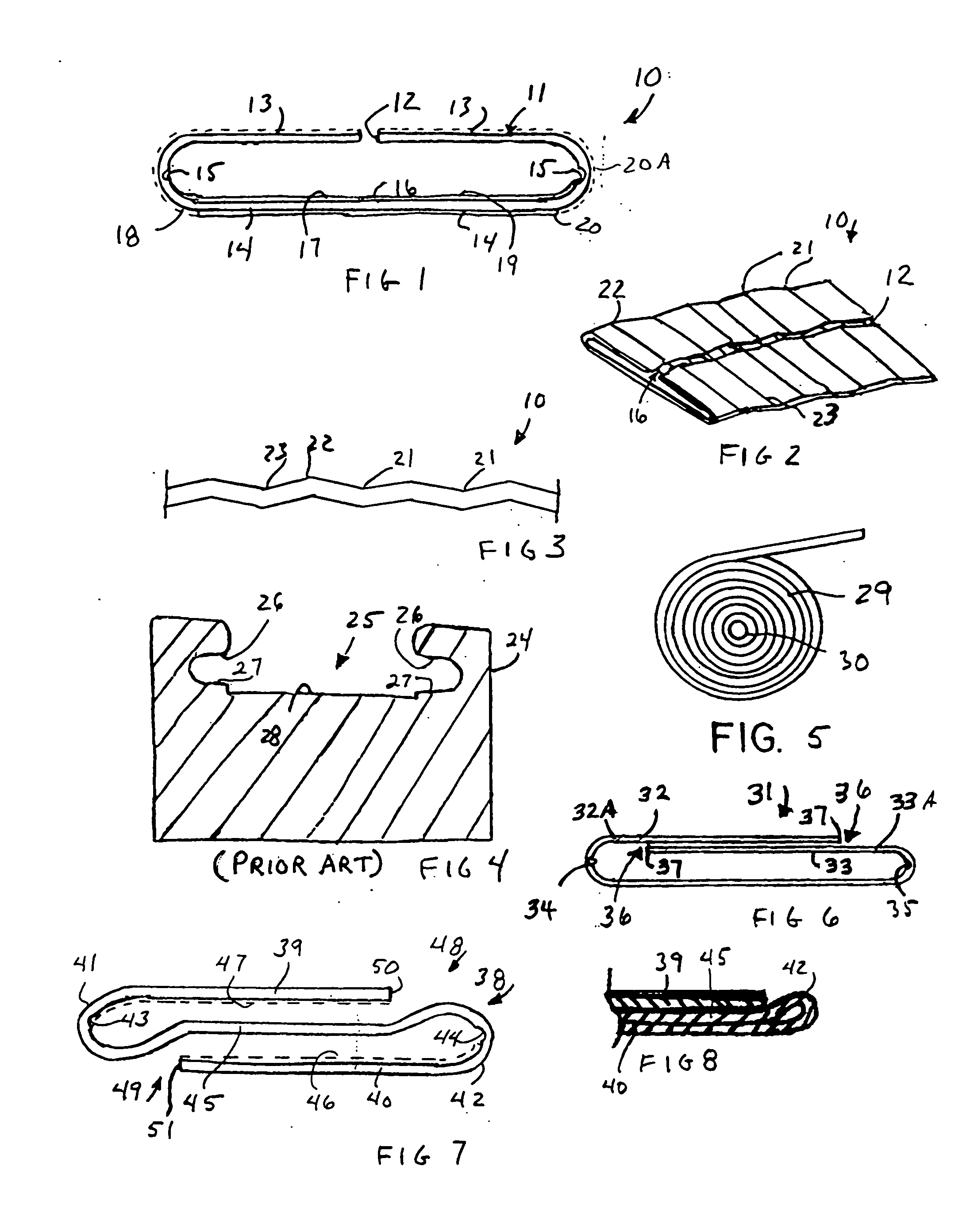
[0034]FIG. 6 illustrates the paperband 31 having partially overlapping side portions 32, 33 defined by longitudinal score lines 34, 35 and edges 37. The section of the paperband 31 between the side portions 32A, 33A do not overlap, form longitudinal lines or narrow areas of weakness 36 since the edge portions are two layers of the multi-ply material which the center portion has three layers of the material and permit bending along 36 of the paperband 31 during turn-up or other uses.

third embodiment

[0035] In FIG. 7, a paperband 38 includes side portions 39 and 40 and a medial or center portion 45 folded to form a generally S-shape. The side portion 39 is folded about longitudinal score line 43 forming a “soft bend”41. The other side portion 40 is similarly folded about longitudinal score line 44 to form a “soft bend”42. Areas of weakness or flexible joints 48 and 49 are created during the transition from three layers to two layers. Adhesive layers 46 and 47 are shown on opposed surfaces of the paperband 38, i.e., an upper surface of side portion 39 and a lower surface of side portion 40. Alternately, the adhesive 46, 47 may be applied simultaneously to both surfaces of center portion 45. This method may be accomplished by feeding the unfolded paperband board vertically to permit the adhesive 46, 47 to be sprayed on or otherwise applied to center portion 45 by any appropriate technology.

[0036] The performance of paperband 38 is similar to that of paperbands 10, 31 in track pull...


PUM

PropertyMeasurementUnit
tensile strengthaaaaaaaaaa
stiffnessaaaaaaaaaa
stretchabilityaaaaaaaaaa

Abstract

Roll of paperband usable in paper web cutting and turn-up systems or in baling includes an elongate multi-ply board having a center portion and side portions, each having an inside and outside edge portions and the inside edge portion being defined by a longitudinal first groove. Each side portion is folded to dispose same in contact with center portion. The paperband includes upper and lower transverse undulations to enable the board to be formed into a roll of paperband without materially affecting its tensile strength. The side edge portions may be located closely adjacent each other without any overlap therebetween so that a longitudinal line of weakness is formed therebetween or may overlap and render weakened edge portions. An adhesive coats the outer surface thereof when the paperband is used for baling.

Description

CROSS REFERENCE TO RELATED APPLICATIONS [0001] This application is related to an application entitled “ROLL OF PAPERBAND” Ser. No. 10 / 617,418, filed Jul. 11, 2003; and an application entitled “ROLL OF PAPERBAND” Ser. No. 10 / 878,727, filed Jun. 28, 2004.STATEMENT REGARDING FEDERALLY SPONSORED RESEARCH OR DEVELOPMENT [0002] Not Applicable. REFERENCE TO A MICROFICHE APPENDIX [0003] Not Applicable. BACKGROUND OF THE INVENTION [0004] 1. Technical Field [0005] This invention relates to a roll of paperband wherein the paperband includes longitudinal indentations and transverse undulations to create a corrugated structure to control stiffness and flexibility of the band as desired. [0006] 2. Prior Art [0007] It is a common practice in the papermaking and packaging industries to employ a paperband or strap that is loaded into a channel of a track assembly and then removed rapidly out of the channel and employed to cut and spool a web of paper onto an empty spool or to be used to wrap around ...

Claims


Application Information

Patent Timeline
Patent Type & Authority Applications(United States)
IPC IPC(8): B32B3/04
CPCB31D1/0056Y10T428/24628B32B3/10B32B7/12B32B29/005B32B29/08B32B2250/26B32B2255/12B32B2255/26B32B2307/54B32B2307/5825B32B2405/00Y10T428/24231Y10T428/2419Y10T428/24264B32B3/04
Inventor RODRIGUEZ, PETER A.
Owner SANDAR IND
Why Eureka
Try Eureka