Retrievable subsea device and method

a subsea device and a technology of a submerged body, applied in the direction of sealing/packing, drilling pipes, borehole/well accessories, etc., can solve the problems of large amount of swarf which has to be circulated out, large amount of metallic swarf to be recovered, potential risk factor is realized, etc., to achieve the effect of minimising the risk of fouling

Active Publication Date: 2019-02-26
SCHLUMBERGER OILFIELD UK LTD
View PDF8 Cites 1 Cited by
  • Summary
  • Abstract
  • Description
  • Claims
  • Application Information

AI Technical Summary

Benefits of technology

[0009]The present invention provides apparatus and a method which allows internal protection of a blow out preventer (B.O.P.) especially a subsea B.O.P. at the wellhead, against deleterious ingress of metallic swarf during circulation thereby minimising the risk of fouling leading to compromise of the equipment.
[0012]The protective device is connected into a work string for run in and is typically within the length of work string and may be spaced from a bottom hole assembly (BHA) including for example a milling tool or drill bit. The work string may be made up for example from drill pipe using standard pin and box joints, and the protective device may be connected into the work string during the usual make up procedure and positioned at a predetermined distance from the BHA for subsequent deployment within the B.O.P. In this way the probability of metallic swarf circulating upwards from a milling tool and becoming trapped in a critical section of the B.O.P. stack, e.g. a cavity including a sealing surface within the B.O.P. is greatly diminished. The sleeve acts as a bridging conduit for return of swarf-contaminated circulation fluid to allow it to bypass the critical components within the B.O.P.
[0020]Where a “drill ahead” operation is conducted immediately after milling out a window in the casing (without pulling out the string first) the running tool may be carried several hundred feet beyond the window and thereby be remote from the B.O.P. In order to anticipate development of a situation where it is deemed necessary to apply a contingency measure requiring the B.O.P. to be fully operational, the work string can be modified to allow retrieval of the protective device of this invention before the running tool or pick up sub can be pulled back to the B.O.P. A suitable modification would be to introduce an auxiliary pick up device that can latch onto the protective device of this invention and allow it to be pulled out of the B.O.P. a sufficient distance to allow any or all of the B.O.P. contingency measures to be operated. This precautionary modification is achievable before run in by introducing a collet at intervals in the make up of the work string behind the running tool / protective device assembly. A series of such auxiliary pick up devices could be conveniently spaced out at intervals of 90 feet or less. It will be understood that on run in the auxiliary pick up devices are stowed but on pull out in an emergency situation, at least one of such pick up devices is deployed, optionally automatically e.g. by contact with a surface of the protective device itself or a surface near to it thereby effecting release of stored energy biasing means, such as by spring loading to allow pulling of the protective device out of the B.O.P. sufficiently. This means that by pulling the work string a relatively short distance the protective device is cleared from the B.O.P. sufficiently to allow full operation thereof without need to pull the work string the full distance required to recover the remote running tool to the B.O.P.

Problems solved by technology

Such a milling operation results in large amounts of swarf which has to be circulated out.
Similarly where a milling operation is required to remove a broken or stuck pipe or tool or any other junk that is obstructing normal operations, large amounts of metallic swarf have to be recovered.
However, when circulation of such swarf-laden fluids is to pass through a blow out preventer (B.O.P.) which has cavities or recesses housing contingency equipment, passages allowing an intervention or coupling of ancillary equipment, a potential risk factor is realised in that each cavity, recess or passage represents a trap for metallic swarf debris.
Where the metallic swarf fouls in such cavities, recesses and passages, the consequences may be that operational use of contingency measures can be compromised.
However such risks are exacerbated when the B.O.P. is located at depth, i.e. at the wellhead on the sea floor, where access is restricted and there is a high dependency on reliability of the contingency measures provided thereby.
The time involved in recovery inspection, and re-running of the subsea B.O.P. to the wellhead for re-installation leads to a high cost which currently appears unavoidable to a prudent operator.
However, cost is not the dominating factor, and the decision to pull the riser and subsea B.O.P. stack is not one to be taken lightly in view of the considerable HSE risks associated with completing the operation.
Handling of the retrieved B.O.P. and riser components involves additional risks to personnel.
Therefore, there are numerous HSE risks associated with these heavy lifting operations.

Method used


Image

  • Retrievable subsea device and method
  • Retrievable subsea device and method

Examples


Embodiment Construction

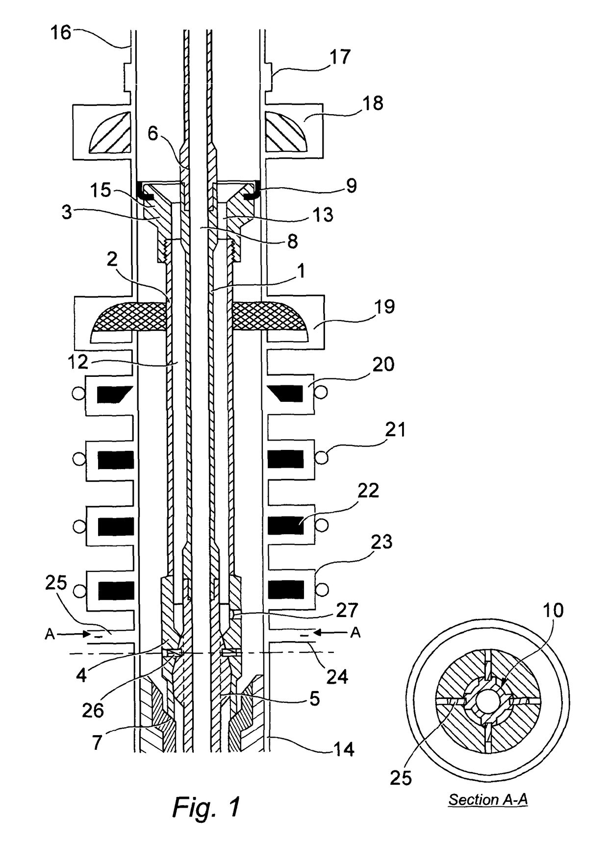
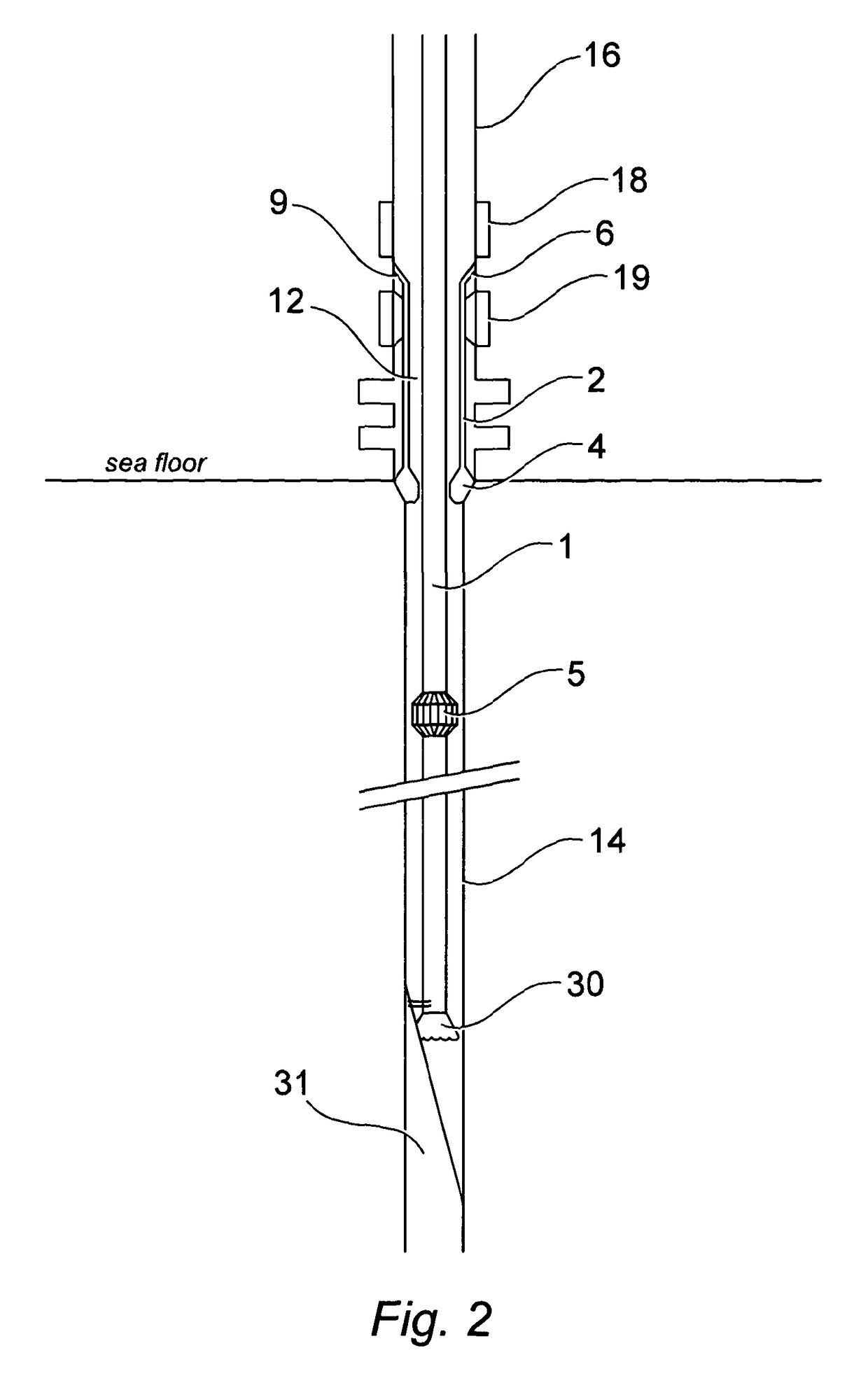
[0037]An embodiment of the protective sleeve device of the invention is illustrated in the accompanying figures and shown deployed upon a workstring within a blow out preventer stack (B.O.P.).

[0038]Referring to FIG. 1, the device comprises a hollow drill pipe or mandrel 1, the mandrel having an axial passage 8 for the passage of drilling fluid, and being connected at an upper end to a drill pipe 6 forming part of a work string in the usual way using pin and box threaded connections. A running tool 5 is connected to the lower part of the mandrel 1 and that in turn is also connected to further drill pipe sections forming the drill string (not shown in FIG. 1) below the device.

[0039]A running tool housing 4 attached to the running tool 5 by shear fastener pins 26 also provides a means of attachment for a protector sleeve 2 spaced from the mandrel 1 to define an annulus 12 within the device to allow fluid flow communication with wellbore annulus above and below the device. The upper end...


PUM


Abstract

A protective device for a blow out preventer stack (B.O.P.), and a sidetracking method using same during an oil-field milling or drilling operation requiring a window to be formed in casing to access a formation, the device having a sleeve assembly and a running tool releasably attached to the sleeve assembly, wherein the running tool comprises a running tool housing connected to the sleeve assembly and a separable running tool body connectable within the length of a work string having a BHA with a mill or bit, the running tool housing being shear pinned to the running tool body for running in hole, wherein the running tool housing is configured to shear from the running tool body during deployment into a cased wellbore to sealingly seat the sleeve assembly within a B.O.P. and form a barrier to ingress of swarf into the B.O.P.

Description

FIELD OF THE INVENTION[0001]The present invention relates to a device deployable upon a workstring during a downhole operation and retrievable with the workstring upon completion of the downhole operation, and especially to a device useful during a milling operation typically required within casing for the purposes of preparing a well for oil and gas production.BACKGROUND TO THE INVENTION[0002]When drilling for oil and gas, a wellbore or borehole of an oil or gas well is typically drilled from surface to a first depth and lined with a steel casing. The casing is located in the wellbore extending from a wellhead provided at surface or seabed level, and is then cemented in place. Following testing and other downhole procedures, the borehole is extended to a second depth and a further section of smaller diameter casing is installed and cemented in place. This process is repeated as necessary until the borehole has been extended to a location where it intersects a producing formation. I...

Claims


Application Information

Patent Timeline
Patent Type & Authority Patents(United States)
IPC IPC(8): E21B29/02E21B29/00E21B17/10E21B33/06E21B33/068
CPCE21B29/002E21B17/1007E21B33/068E21B33/062E21B33/06
Inventor TELFER, GEORGE
Owner SCHLUMBERGER OILFIELD UK LTD
Why Eureka
Try Eureka