Locating and analyzing perforator flaps for plastic and reconstructive surgery

a perforator and perforation technology, applied in the field of locating and analyzing perforator flaps for plastic and reconstructive surgery, can solve the problems of insufficient simple visual observation, insufficient rapid accumulation of fluorescence, and inability to locate and evaluate perforator flaps, etc., to facilitate rapid comprehension of image features

Active Publication Date: 2019-03-05
STRYKER EUROPEAN OPERATIONS LIMITED
View PDF479 Cites 9 Cited by
  • Summary
  • Abstract
  • Description
  • Claims
  • Application Information

AI Technical Summary

Benefits of technology

[0009]The various image processing steps process the image pixels independently and compute a unique numerical metric for each pixel in the input sequence observed across the entire time of the acquisition or a selected temporal sub-range. Each image output is thus a numerical array having the same dimensions, i.e. number and arrangement of pixels, as a frame in the input image sequence. Thus, the processed image can be displayed, for example, as a three-dimensional representation, for example a contour map, of the computed pixel values across the imaged area, or as a color-coded two-dimensional image or a relief map. Such image representations facilitate rapid comprehension of image features and comparison between regions on the images, in this case the location of the perforators under the skin.

Problems solved by technology

Localization and evaluation of perforators is a painstaking and time-consuming process.
Such an approach entails considerable expense and has the additional complication that the surgeon must mentally correlate the images from the previously acquired 3D modality with the current 2D view of the patient now lying on the operating table.
Here, simple visual observation while fluorescence rapidly accumulates and dissipates does not suffice.
For example, the tendency of residual ICG from successive injections to accumulate in tissue and to gradually raise the background brightness with each injection further confounds easy visual discrimination of the best candidate perforators.
In addition, ICG sometimes moves exceedingly slowly over several minutes making such on-the-fly analysis very challenging and subjective.
These questions are difficult to answer on a subjective basis.

Method used


Image

  • Locating and analyzing perforator flaps for plastic and reconstructive surgery
  • Locating and analyzing perforator flaps for plastic and reconstructive surgery
  • Locating and analyzing perforator flaps for plastic and reconstructive surgery

Examples


Embodiment Construction

[0023]The invention is directed to preoperative determination of the location of perforator vessels in perforator flaps by a non-invasive method, before any incision is made.

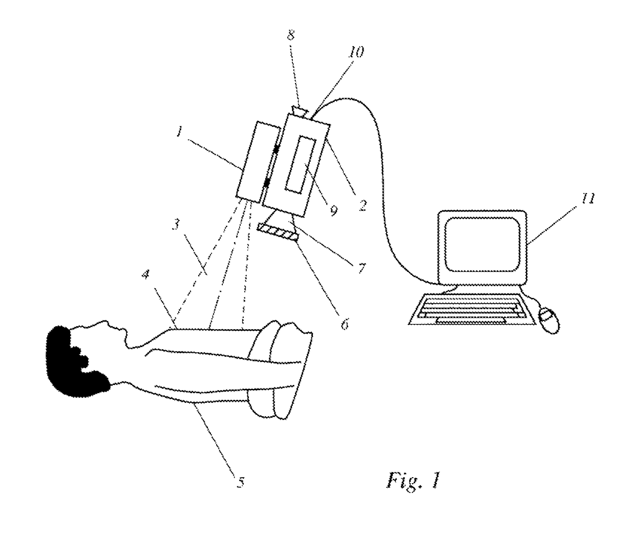
[0024]FIG. 1 shows schematically a device for a non-invasive, through the skin determination of tissue perfusion in operative, in particular preoperative, applications by ICG fluorescence imaging. An infrared light source, for example, one or more diode lasers or LEDs, with a peak emission of about 780-800 nm for exciting fluorescence in ICG is located inside housing 1. The fluorescence signal is detected by a CCD camera 2 having adequate near-IR sensitivity; such cameras are commercially available from several vendors (Hitachi, Hamamatsu, etc.). The CCD camera 2 may have a viewfinder 8, but the image may also be viewed during the operation on an external monitor which may be part of an electronic image processing and evaluation system 11.

[0025]A light beam 3, which may be a divergent or a scanned beam, emerges ...


PUM


Abstract

A method and an apparatus for preoperative identification of a perforator vessel for plastic and / or reconstructive surgery using ICG fluorescence angiography imaging are disclosed. Time-resolved image processing is used to highlight perforator locations and to enable visual discrimination among candidate perforators by various computed metrics. Based on these metrics, the surgeon is able to interactively locate and select perforator vessels suitable for plastic and reconstructive surgery.

Description

CROSS-REFERENCE TO RELATED APPLICATIONS[0001]This application is a continuation-in-part of prior filed copending PCT International application no. PCT / IB2009 / 05700, filed Apr. 14, 2009, which designated the United States and has been published as International Publication No. WO / 2009 / 127972 in the English language, and which claims the benefit of U.S. Provisional Application Ser. No. 61 / 044,779, filed Apr. 14, 2008.[0002]This application also claims the benefit of prior filed U.S. provisional Application No. 61 / 243,688, filed Sep. 18, 2009, the entire contents of which are incorporated herein by reference.BACKGROUND OF THE INVENTION[0003]Plastic and reconstructive surgery often entails the localization and clinical evaluation of a flap of skin and subcutaneous tissue which is supplied by isolated perforator vessels and that is potentially suitable for grafting in another part of the body. Perforators pass from their source vessel to the skin surface, either through or between deep m...

Claims


Application Information

Patent Timeline
Patent Type & Authority Patents(United States)
IPC IPC(8): A61B5/00A61B17/00
CPCA61B5/489A61B5/413A61B5/0059A61B2017/00792
Inventor DVORSKY, PETERGOYETTE, DAVID MARK HENRI
Owner STRYKER EUROPEAN OPERATIONS LIMITED
Why Eureka
Try Eureka