
Firearm sound suppressor

a technology for suppressors and firearms, applied in the direction of weapons, weapon components, etc., can solve the problems of difficult cleaning, damage to the baffle or other internal components, and the deterioration of the sound suppression system, so as to reduce the muzzle blast and noise of firearms

Inactive Publication Date: 2019-03-05
APD MFG LLC
View PDF8 Cites 9 Cited by
  • Summary
  • Abstract
  • Description
  • Claims
  • Application Information

AI Technical Summary

Benefits of technology

The modular design facilitates easy cleaning and repair, improves noise reduction by dissipating gases through multiple pathways, and enhances compatibility with various firearm systems by allowing for adjustable configurations.

Problems solved by technology

Over time, the baffles and components can become dirty from the gases and debris carried in them.
Because the components are fixed, they can be difficult to clean.
Further, if a silencer is misaligned with a muzzle, a bullet can damage one of the baffles or other internal components.
Due to the fixed connections, it can be difficult if not impossible to replace the damaged component and repair the suppressor.
Where welded, the cans can be difficult to replace or change out when damaged due to a misaligned bullet or external impacts to the can.
Where solely threaded together, the threads sometimes might not offer a perfect seal to prevent propellant gases from escaping therethrough.
This can result in the discharge of hot propellant gases and associated debris where the components are joined.
While effective in many cases, the single gas pathway might present issues in effectively dissipating the gases and controlling expansion.
While this can offer more area within the can to control and dissipate expanding gases, it can present issues when a user utilizes the silencer with different weapons.
For example, the silencer and in particular the over the barrel expansion chamber may readily fit over a standard government profile barrel, however, when the user tries to put the silencer on a firearm with a bull barrel or odd front handguard, the over the barrel expansion chamber might not fit.
This can limit the versatility of the silencer and its compatibility with different weapon systems.

Method used


Image

  • Firearm sound suppressor
  • Firearm sound suppressor
  • Firearm sound suppressor

Examples


Embodiment Construction

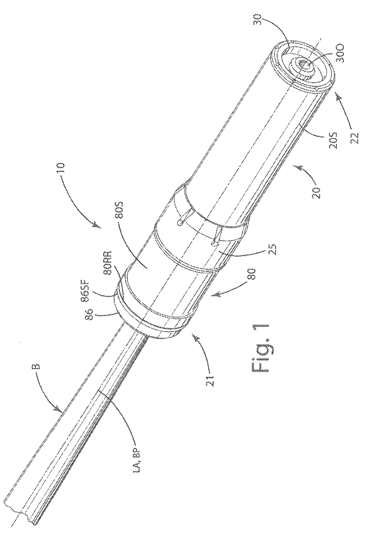
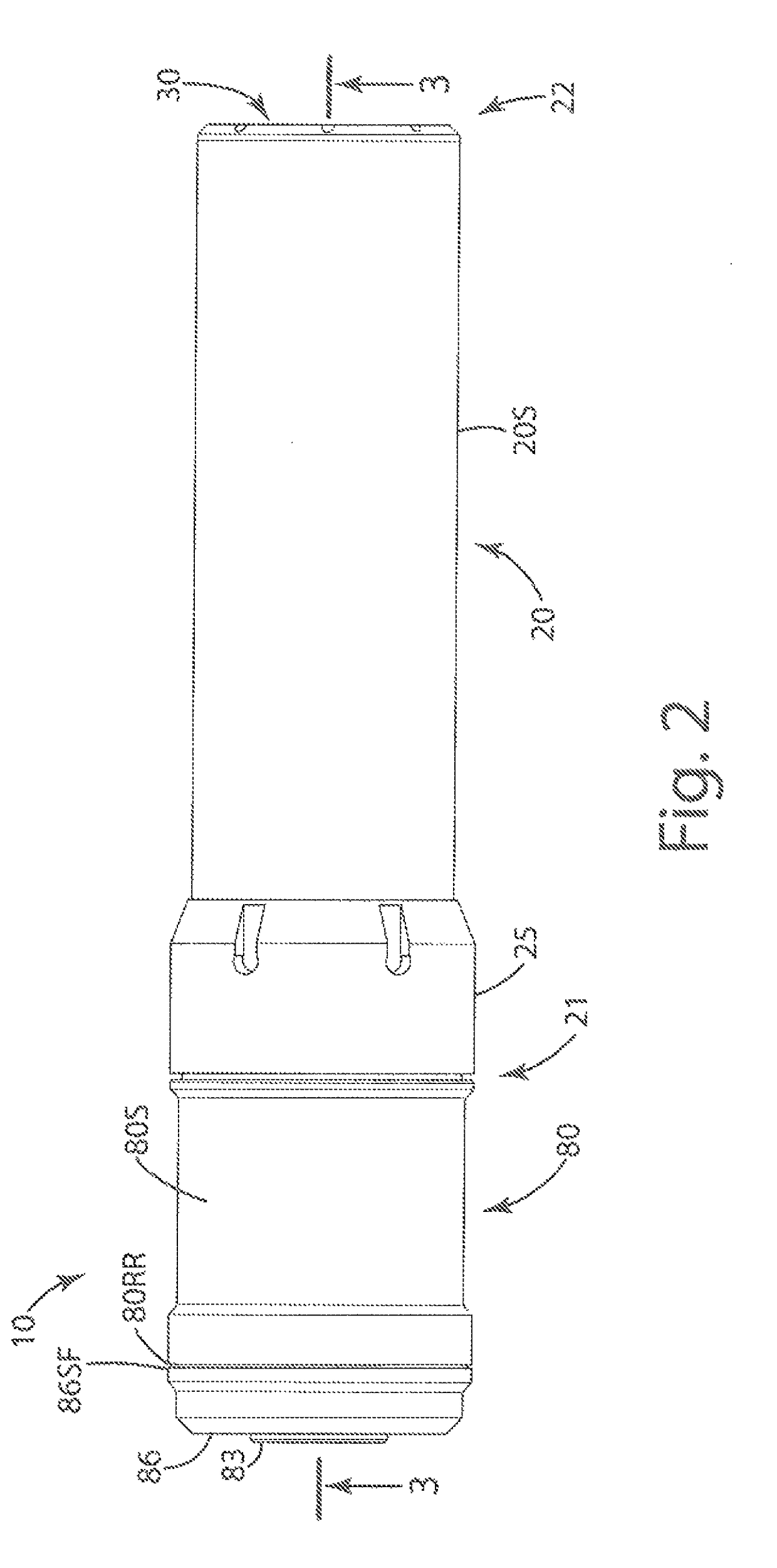
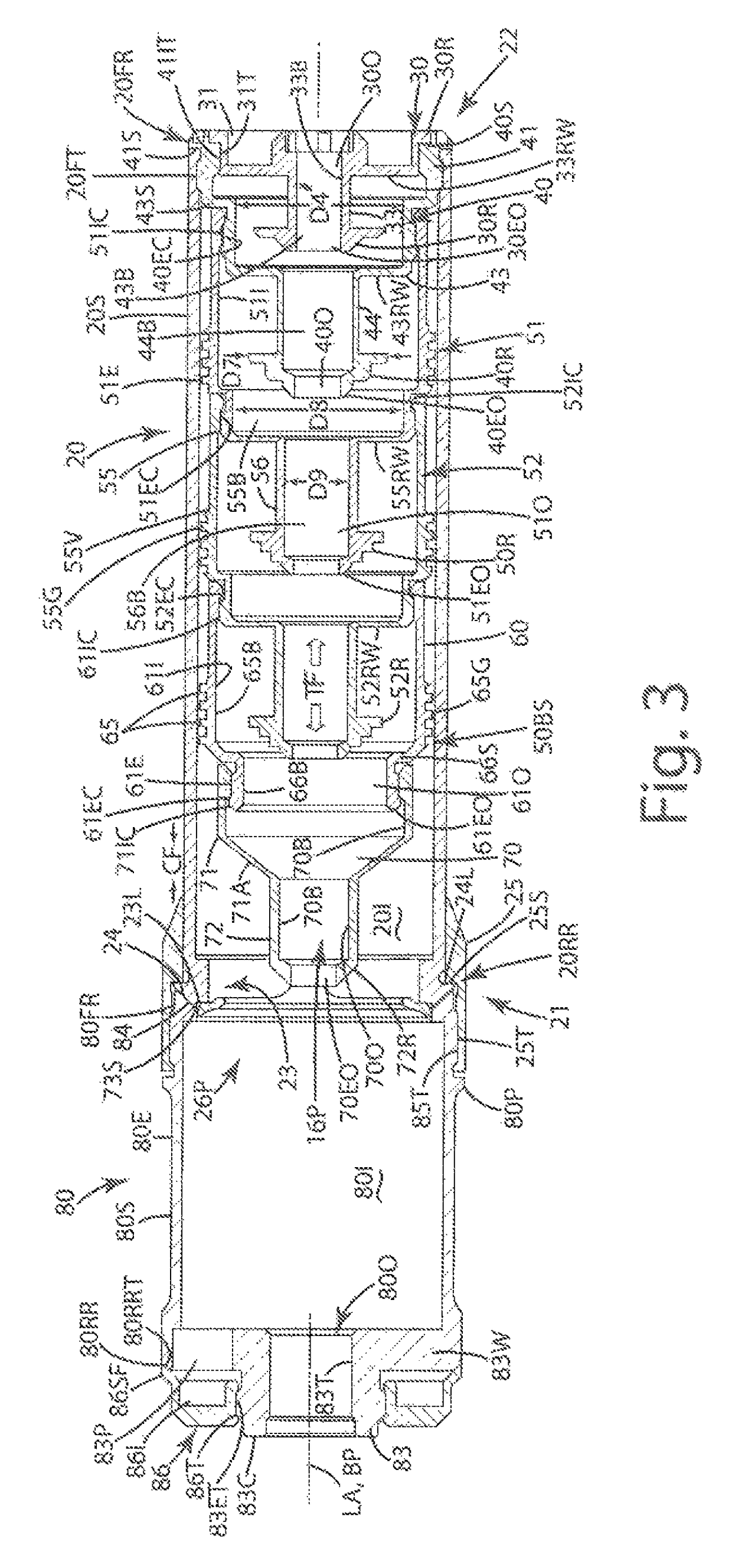
[0030]A current embodiment of the suppressor is illustrated in FIGS. 1-12, and generally designated 10. The suppressor 10, also referred to as a silencer herein, can include an elongate baffle tube 20 that can house a front end cap insert 30 and a front end cap 40, along with one or more baffle modules 50, 60 and a blast baffle 70. The baffle tube 20 can be joined with an expansion chamber tube 80 configured to lower the pressure and temperature of the discharged propellant gases, from the firearm muzzle or muzzle break to which it is attached, to a level beneficial to the function of the components in the remaining paths through the silencer. As described later in connection with FIGS. 10-12, the suppressor 10 can include an optional over the barrel expansion tube or chamber 90, which is by its namesake, configured to extend rearward over a portion of the barrel B of the firearm to which the suppressor 10 is joined. This over the barrel expansion tube 90, however, can be removable ...


PUM


Abstract

A suppressor for reducing muzzle blast and noise of firearms. The suppressor can include a baffle tube including a stack of baffle modules that are removably coupled to one another, and an optional blast baffle, end cap and end cap insert. The stack can be independently supported from both bullet entry and exit ends of the tube, with the stack under tension and the tube under compression. Two or more tubes of can be joined with one another at ends having corresponding sealing flanges, which also can center the tubes relative to one another. A blast baffle can separate pressurized gas into a first pathway through the baffle stack and a second pathway between the baffle modules and the baffle tube. The baffle tube and / or an expansion chamber tube can include a rearward end cap that is removable and replaceable with an over the barrel expansion tube.

Description

BACKGROUND OF THE INVENTION[0001]The present invention relates to sound suppressors and silencers for firearms, and more particularly to a suppressor having a modular system of baffles, a blast tube and an expansion tube removably and detachably joined with one another to facilitate customization and repair of components of the suppressor.[0002]Firearm suppressors, also known as silencers, reduce the audible noise or sharp report of a firearm by controlling and reducing the energy levels of propellant gases discharged from the muzzle of the firearm. Most conventional suppressors include a tube or “can” having a series of baffles therein that control and delay the flow, expansion, and exit of propellant gases from the silencer. In so doing, the silencers achieve a corresponding reduction in the noise produced by the exiting propellant gases.[0003]Many conventional suppressors include baffles and internal components that are fixedly welded to the silencer can and / or one another. Over ...

Claims


Application Information

Patent Timeline
Patent Type & Authority Patents(United States)
IPC IPC(8): F41A21/30
CPCF41A21/30
Inventor ADAMSON, JR., DAVID K.
Owner APD MFG LLC
Learn More