Cable connector with plate-like mounting portion

a technology of connectors and mounting parts, applied in the field of connectors, can solve problems such as the reduction of the amount of outgoing light emitted by illumination devices, and achieve the effect of lowering the protruding height of the connector

Active Publication Date: 2019-03-05
JAPAN AVIATION ELECTRONICS IND LTD
View PDF31 Cites 1 Cited by
  • Summary
  • Abstract
  • Description
  • Claims
  • Application Information

AI Technical Summary

Benefits of technology

[0010]According to the one aspect of this invention, when the connector is mounted to the board, the mounting portion protrudes from one surface of the board while the cable fitting portion protrudes from the other surface of the board. As the mounting portion is formed by a plate-like member, it is possible to lower a protruding height of the connector on a side of the mounting portion.

Problems solved by technology

As mentioned above, there is a problem that the connector interrupts some of the light beams emitted by the LED along the board and, as a result, causes a reduction in amount of outgoing light emitted by an illumination device comprising the LED as a light source.

Method used


Image

  • Cable connector with plate-like mounting portion
  • Cable connector with plate-like mounting portion
  • Cable connector with plate-like mounting portion

Examples


first modification

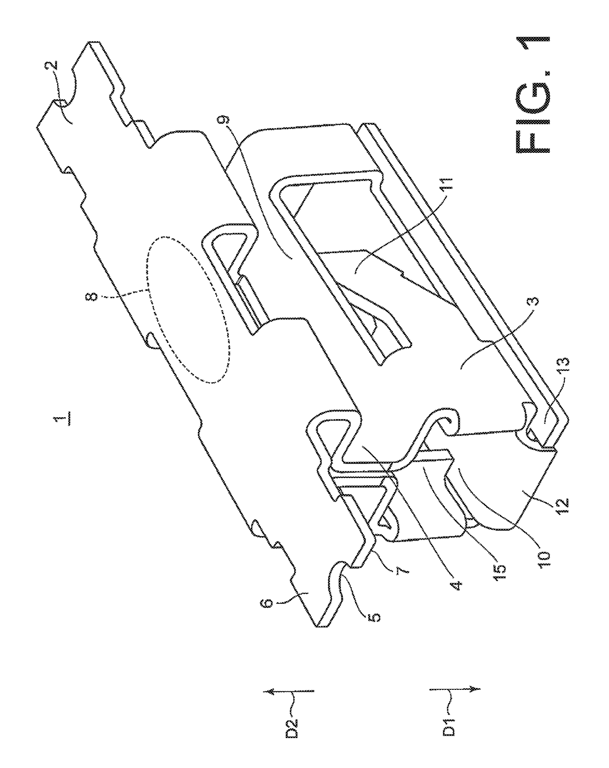
[0082]Referring to FIGS. 17 and 18, a connector 30 as a first modification of the connector 1 will be described. The connector 30 illustrated in the figures is different from the connector 1 in that the mounting portion 2 has two bending portions 31.

[0083]Specifically, the connector 30 has the two bending portions 31 faced to each other with a center portion of the mounting portion 2, including the sucking portion 8, interposed therebetween. The center portion between the two bending portions 31 forms a recessed portion depressed towards the cable fitting portion 3. As illustrated in FIG. 18, both of the two board contact portions 7 are disposed on the mount surface 21. On the other hand, the center portion between the two bending portions 31 is configured so that the sucking portion 8 is located at a position lower than a mount surface level 32 depicted by a dotted line representing a height of the mount surface 21 and higher than the rear surface 22.

[0084]With the above-mentioned ...

second modification

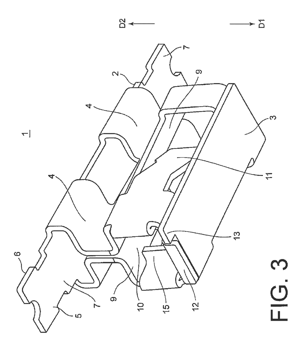
[0087]Referring to FIGS. 19, 20, 21A and 21B, a connector 40 as a second modification of the connector 1 will be described. The connector 1 has the upper cover 9, in addition to the mounting portion 2, to cover the area above the cable contact portions 11. In association therewith, the connector 1 has the connecting portion 4 to connect the mounting portion 2 and the upper cover 9. In contrast, the connector 40 is different from the connector 1 in that the area above the cable contact portions 11 is directly covered by the mounting portion 2. Therefore, the connector 40 does not have the connecting portion 4 and the upper cover 9. The cable contact portions 11 are directly faced to the mounting portion 2.

[0088]As described above, the connector 40 is simplified in structure as compared with the connector 1 and, therefore, is easy to manufacture. As the connector 40 requires a metal plate having a smaller area, it is possible to reduce a manufacturing cost.

[0089]As illustrated in FIG....

third modification

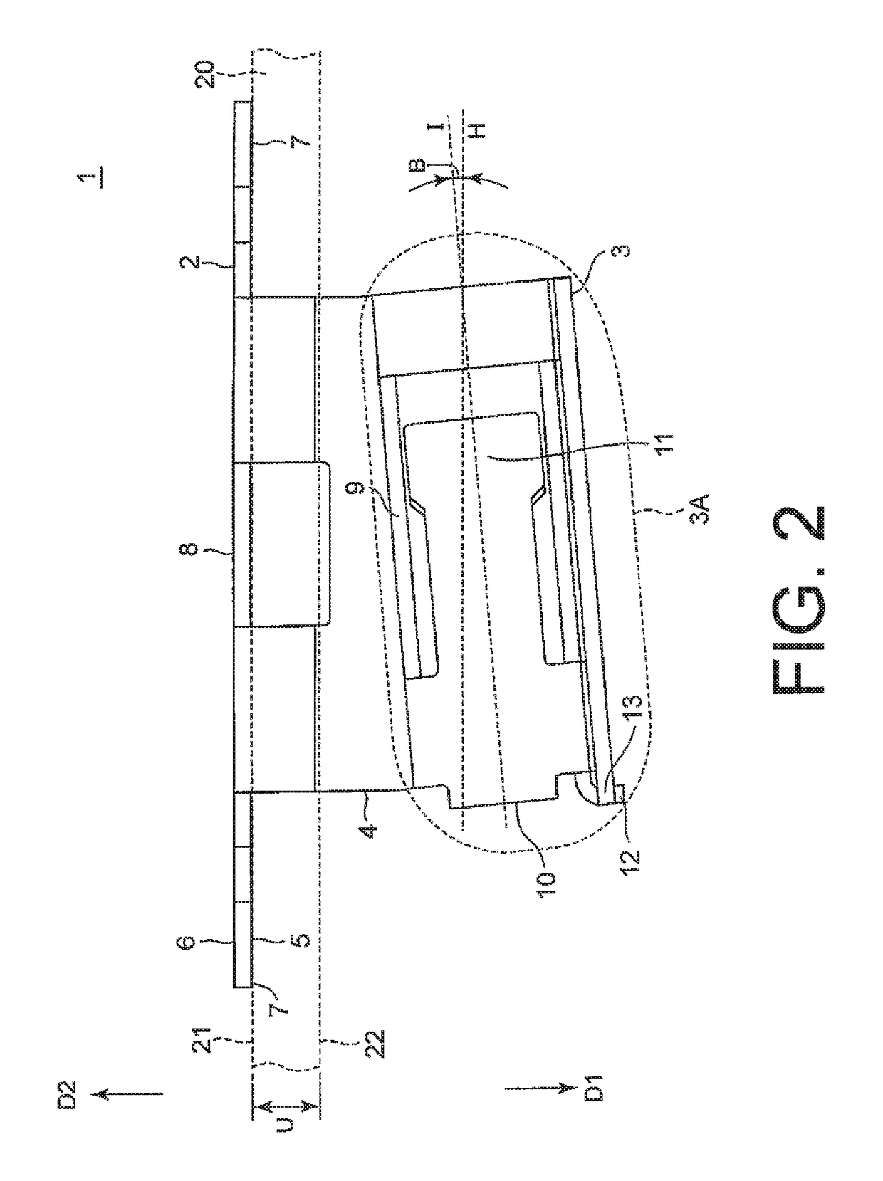
[0093]Referring to FIGS. 22 and 23, description will be made of a connector 50 as a third modification of the connector 1. In the connector 1, the inserting direction I of inserting the coated conductor 16 into the receiving portion 3A is inclined by the angle B with respect to the mount surface 21 of the board 20 and the first flat surface 5 of the mounting portion 2. In contrast, in the connector 50, the inserting direction I is parallel to the mount surface 21 of the board 20 and the first flat surface 5 of the mounting portion 2. The coated conductor 16 inserted into the receiving portion 3A of the connector 50 is received and held in the inserting direction I.

[0094]In the connector 50, a bottom surface of the receiving portion 3A can be kept in parallel to the board 20. Therefore, when the board 20 with the connector 50 mounted thereto is disposed on another board, the board 20 is easily stabilized.

[0095]Although his invention has been described above in connection with the emb...


PUM


Abstract

A connector has a mounting portion of a plate-like shape and a cable fitting portion protruding from the mounting portion in a first direction. The mounting portion has a fixing portion disposed on a first flat surface faced to the first direction and adapted to be fixed to a board, and a flat portion disposed on a second flat surface faced to a second direction opposite to the first direction. The cable fitting portion has a receiving portion adapted to receive a cable, an opening portion formed at one end of the receiving portion and allowing the cable to be inserted therethrough, and a cable contact portion to be electrically connected to the cable.

Description

[0001]This application is based upon and claims the benefit of priority from Japanese Patent Application No. 2016-143090 filed on Jul. 21, 2016, the disclosure of which is incorporated herein in its entirety by reference.TECHNICAL FIELD[0002]This invention relates to a connector and, in particular, to a connector adapted to be mounted to a board and to receive a cable. In this application, the cable means a linear conductor and includes, in particular, a coated conductor.BACKGROUND ART[0003]As a connector of the type, proposal is made of a surface-mount connector described in JP-A-2010-514138 (hereinafter referred to as Patent Document 1). As shown in FIG. 24, the surface-mount connector described in Patent Document 1 is configured as, for example, a low-profile surface-mount electrical connector (SMEC) 720 which is disposed on one surface of a board 730 together with a light emitting diode (LED) 750 and a resistor 740. In FIG. 24, directions perpendicular to the board 730 and going...

Claims


Application Information

Patent Timeline
Patent Type & Authority Patents(United States)
IPC IPC(8): H01R4/48H01R12/53F21V23/06H01R43/16H01R12/58H01R12/57F21Y115/10
CPCH01R4/4818F21V23/06H01R12/53H01R43/16H01R12/57H01R12/58F21Y2115/10H01R4/48185
Inventor URANO, TETSU
Owner JAPAN AVIATION ELECTRONICS IND LTD
Why Eureka
Try Eureka