Method of manufacturing electrode for lithium secondary batteries

a lithium secondary battery and manufacturing method technology, applied in the direction of electrode manufacturing process, cell components, shaping/stretching tubular fabrics, etc., can solve the problems of short-circuit failure of the battery, difficult to form a flat and smooth surface, and formation of protrusions on the electrode surface, so as to reduce the failure of products and increase the productivity of manufacturing the battery using the electrode

Inactive Publication Date: 2010-06-01
SANYO ELECTRIC CO LTD
View PDF32 Cites 0 Cited by
  • Summary
  • Abstract
  • Description
  • Claims
  • Application Information

AI Technical Summary

Benefits of technology

[0012]The above-described manufacturing method reduces the heights of the protrusions adhered on the electrode surfaces by compressing the electrode surfaces after depositing the thin film, and therefore reduces short-circuit failures in the batteries that employ the electrodes produced according to the method.
[0013]As described in the following examples, the short-circuiting of the battery resulting from the protrusions formed on the electrode surfaces due to splash is dependent on the height of the protruding portions. The probability of the short-circuiting increases when the height of the protrusions exceeds a certain value. Therefore, by controlling the height of the protrusions formed on the electrode surfaces to be a predetermined value of 80 μm or less, the short-circuit failures can be lessened. In the present invention, it is preferable to use pressure rollers, which can be incorporated in the thin-film deposition system so that the manufacturing process can be simplified, as the method for compressing the electrode surface.
[0014]When carrying out the pressing process for the electrode surfaces with the use of pressure rollers, the heights of the protrusions can be reduced without causing adverse effects on battery performance if the gap between the pressure rollers is set at about 20% to about 100% of the current collector thickness in the compression process. If the degree of the compression is too low, the effect of reducing the heights of the protrusions will be small, while if the degree of the compression is too high, the silicon thin film may peel off or the current collector may rupture.
[0015]It is preferable that the current collector to be used in the present invention be formed of a metal that does not alloy with lithium. Examples of such a material include copper, alloys containing copper, nickel, and stainless steels. Examples of the alloys containing copper include phosphor bronze and red brass. When the surfaces or the entirety of the current collector is composed of copper, which has relatively low hardness, among these examples, an effect of burying the protrusions, formed on the electrode surface due to the splash, into the current collector in the compression process is attained, which synergistically enhances the effect of reducing the heights of the protrusions.
[0017]The present invention makes it possible to provide an electrode for lithium secondary batteries that has a thin film deposited on the current collector and that has a flat and smooth surface, and thus to reduce the failure of products dramatically. Therefore, the productivity of manufacturing the battery employing the electrode increases.

Problems solved by technology

However, in the process of forming the thin film used for the electrode, it is difficult to form a flat and smooth surface, and protrusions form on the surface.
When such an electrode is used to fabricate a battery, the protrusions formed on the electrode surfaces penetrate the separator and come into contact with the counter electrode, causing a short-circuit failure of the battery.
These particles adhere onto the electrode surface, and result in formation of protrusions on the electrode surface.
Nevertheless, it has been difficult to completely prevent the bumping of evaporation source material.
In particular, in the case of depositing a silicon thin film, techniques to prepare the evaporation source material and to control the procedure of heating the evaporation source material for preventing the bumping have not yet been established and it has been difficult to prevent the bumping phenomenon over a long time period.

Method used


Image

  • Method of manufacturing electrode for lithium secondary batteries
  • Method of manufacturing electrode for lithium secondary batteries
  • Method of manufacturing electrode for lithium secondary batteries

Examples


embodiments

Preparation of Electrode

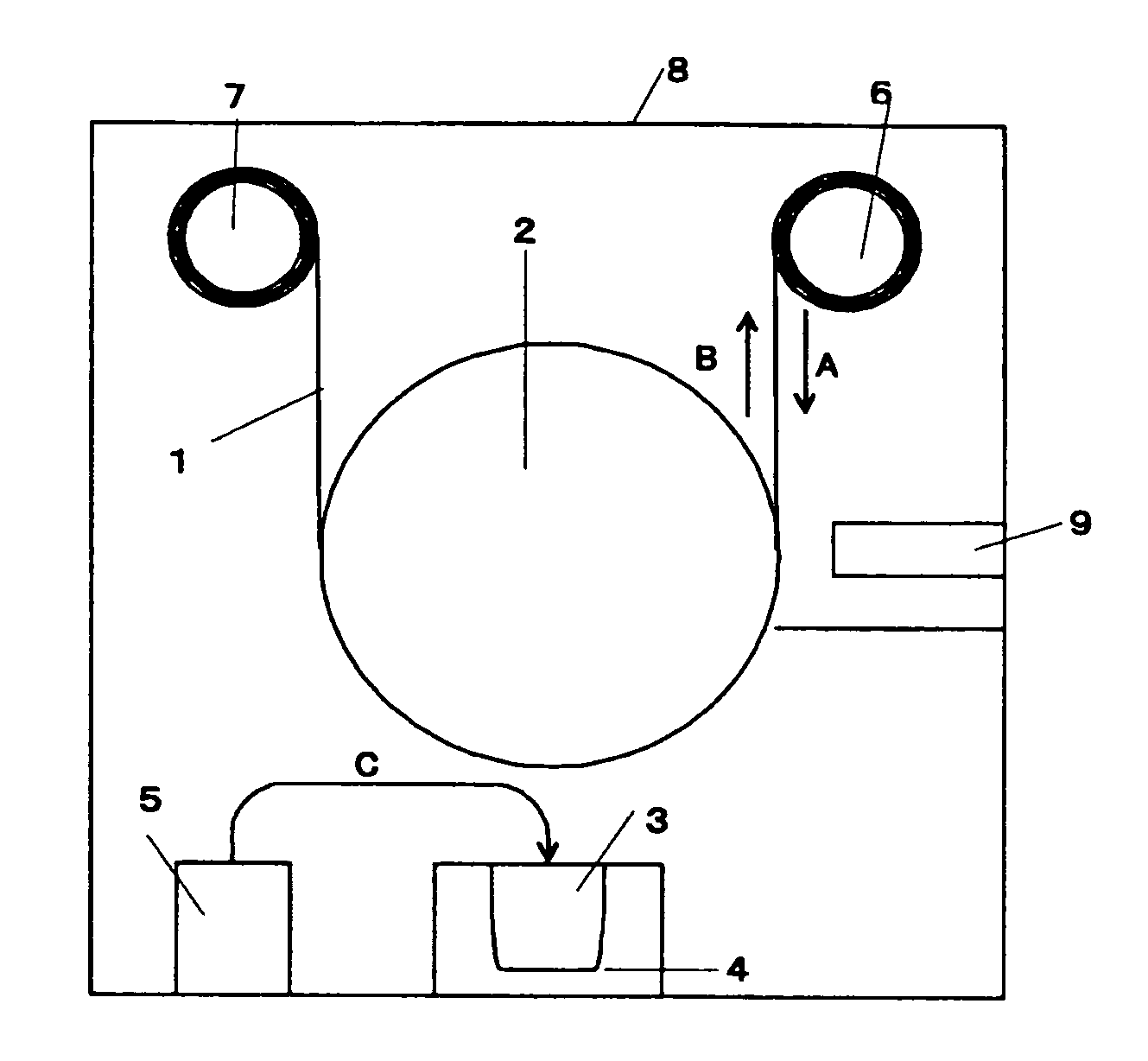
[0024]Copper was deposited on surfaces of a rolled copper foil (thickness 26 mm) by an electrolytic process to roughen the surfaces, and the surface-roughed copper foil was used as the current collector. The surfaces of the current collector had an arithmetical mean roughness Ra of 0.5 μm. Arithmetical mean roughness Ra is defined in Japanese Industrial Standard (JIS) B 0601, and it can be measured by a contact probe profilometer. The use of the surface-roughed copper foil can prevent a silicon thin film from peeling off from the current collector. Such peeling occurs due to the film stress of the silicon thin film or the stress originating from the expansion / shrinkage in volume of the silicon thin film during charge / discharge. On the current collector thus prepared, a silicon thin film was deposited in the following manner, using the thin-film deposition system as shown in FIG. 1.

[0025]The current collector 1 thus prepared was wound around the roller 6, and ...


PUM

PropertyMeasurementUnit
heightaaaaaaaaaa
thicknessaaaaaaaaaa
arithmetical mean roughnessaaaaaaaaaa

Abstract

A method of manufacturing an electrode for a lithium secondary battery in which a thin film of active material is deposited on a current collector is provided that eliminates adverse effects on the battery caused by protrusions adhered on an electrode surface. The method of manufacturing an electrode for lithium secondary batteries includes depositing a thin film of active material on a current collector using thin-film deposition equipment as shown in FIG. 1, and performing a compression process after depositing the thin film, whereby the heights of protrusions formed on the electrode surface are reduced.

Description

BACKGROUND OF THE INVENTION[0001]1. Field of the Invention[0002]The present invention relates to a method of manufacturing an electrode used for lithium secondary batteries.[0003]2. Description of Related Art[0004]Silicon is a material that can be alloyed with lithium. Because of its large theoretical capacity, silicon has received attention as an electrode material that achieves high energy density for lithium secondary batteries. Published PCT Application WO01 / 029912, which is assigned to the assignee of the present invention, proposes a lithium secondary battery electrode in which a thin film composed of silicon is formed on a current collector, as an electrode for a lithium secondary battery that exhibits high charge-discharge capacity and good charge-discharge cycle performance.[0005]However, in the process of forming the thin film used for the electrode, it is difficult to form a flat and smooth surface, and protrusions form on the surface. When such an electrode is used to fa...

Claims


Application Information

Patent Timeline
Patent Type & Authority Patents(United States)
IPC IPC(8): B05D5/12B05D3/12H01M4/02H01M4/13H01M4/134H01M4/139H01M4/1395H01M4/38H01M4/66
CPCH01M4/0404H01M4/0421H01M4/0435H01M4/134H01M4/139H01M4/131Y02E60/122H01M4/38H01M4/525H01M4/661H01M10/052H01M4/386Y02E60/10
Inventor HIRASE, MASAKIYAGI, HIROMASAJITO, DAIZOKOBAYASHI, KEISAYAMA, KATSUNOBU
Owner SANYO ELECTRIC CO LTD
Why Eureka
Try Eureka