Receptacle connector

a technology of a receptacle and a connector is applied in the direction of coupling devices, two-part coupling devices, electrical devices, etc., which can solve the problems of deterioration of the transmission and reception characteristics of the built-in antenna, and achieve the effect of preventing reducing the influence of electrostatic discharg

Active Publication Date: 2019-03-05
JAPAN AVIATION ELECTRONICS IND LTD
View PDF19 Cites 1 Cited by
  • Summary
  • Abstract
  • Description
  • Claims
  • Application Information

AI Technical Summary

Benefits of technology

[0010]The present invention has been made to solve the conventional problem described above and is aimed at providing a receptacle connector that can surely have a predetermined strength and mitigate the influence of electrostatic discharge while preventing the transmission and reception characteristics of a built-in antenna in an electronic device from deteriorating.

Problems solved by technology

In portable electronic devices such as mobile phones and smartphones, typically, a built-in antenna is disposed along an inner surface of a housing of an electronic device in order to have improved transmission and reception of radio waves; however, when a metal surface forming a ground pattern is present near the built-in antenna, even if the metal surface is situated further inside the housing than the built-in antenna, the transmission and reception characteristics of the built-in antenna may deteriorate due to the influence of the metal surface.

Method used


Image

  • Receptacle connector
  • Receptacle connector
  • Receptacle connector

Examples


embodiment 1

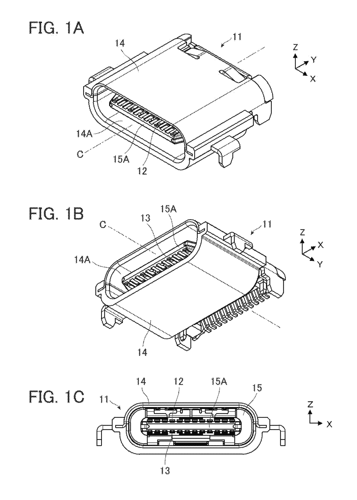
[0032]FIGS. 1A to 1C show a receptacle connector 11 according to Embodiment 1. The receptacle connector 11 is to be mounted on a substrate in a portable electronic device such as a smartphone, and includes a plurality of first contacts 12 that extend in a fitting axis C direction and are arranged in a direction perpendicular to the fitting axis C and a plurality of second contacts 13 that extend in the fitting axis C direction and are arranged parallel to the first contacts 12.

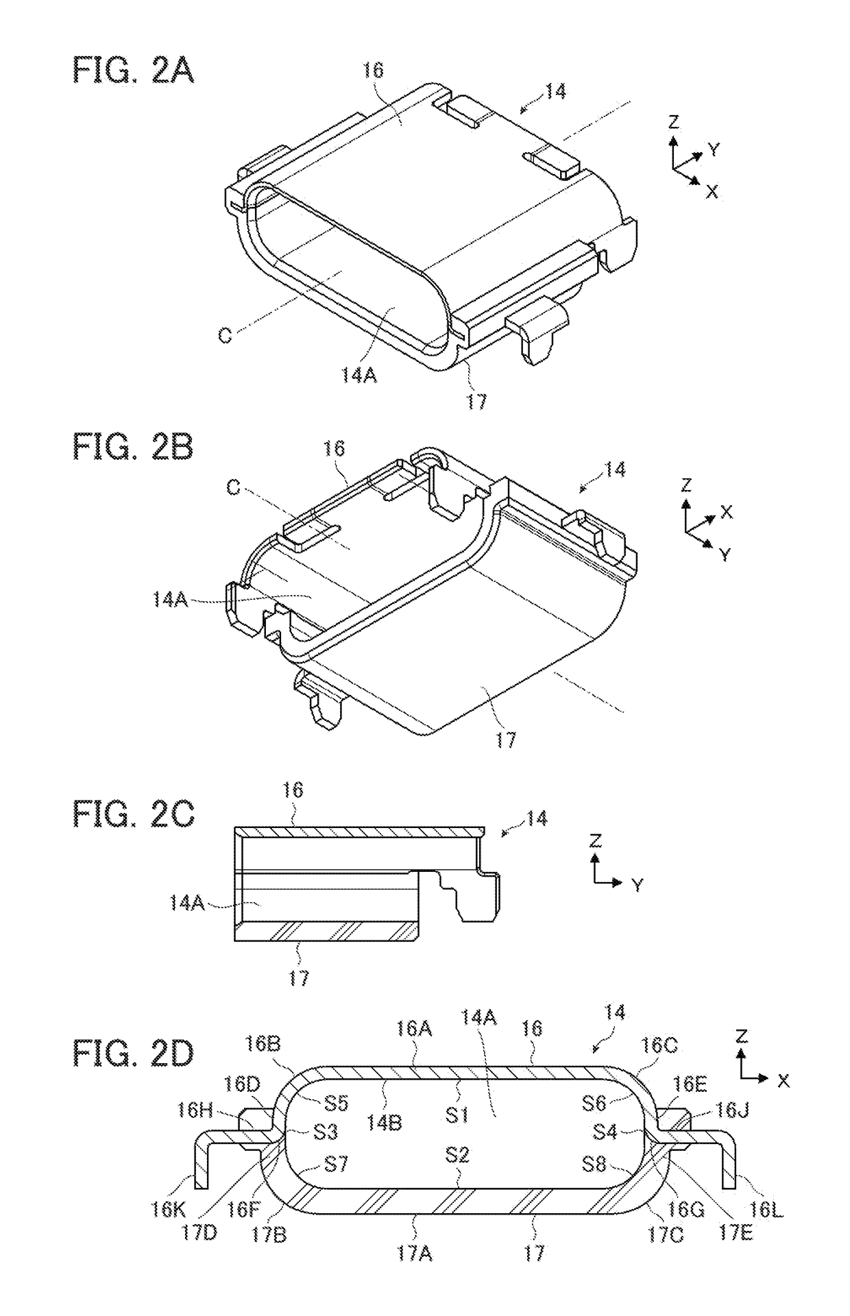
[0033]A peripheral shell 14 extending along the fitting axis C is disposed to cover the periphery of the front end portions, in the fitting axis C direction, of the first contacts 12 and second contacts 13, and a counter connector accommodating portion 14A into which a counter connector (not shown) is to be inserted is formed inside the peripheral shell 14. An insulator 15 made of insulating resin is disposed inside the counter connector accommodating portion 14A and retains the first contacts 12 and the secon...

embodiment 2

[0061]FIGS. 6A to 6C show a receptacle connector 21 according to Embodiment 2. The receptacle connector 21 is configured to have a peripheral shell 24 in place of the peripheral shell 14 in the receptacle connector 11 of Embodiment 1, and the other components are the same as those of the receptacle connector 11.

[0062]Specifically, the peripheral shell 24 extending along the fitting axis C is disposed to cover the periphery of the front end portions, in the fitting axis C direction, of the first contacts 12 and second contacts 13, and a counter connector accommodating portion 24A into which a counter connector (not shown) is to be inserted is formed inside the peripheral shell 24. The +Y directional end of the counter connector accommodating portion 24A is blocked by the insulator 15, and the −Y directional end of the counter connector accommodating portion 24A opens for insertion of a counter connector (not shown).

[0063]The structure of the peripheral shell 24 is shown in FIGS. 7A t...


PUM


Abstract

A receptacle connector includes a peripheral shell with a counter connector accommodating portion formed therein and opening in a fitting direction, the peripheral shell is composed of a metal portion and a resin portion, the peripheral shell has an inner peripheral surface of tetragonal tube shape with rounded corners, the inner peripheral surface being formed by one first metal flat portion, two metal curved portions and two second metal flat portions of the metal portion and one first resin flat portion, two resin curved portions and two second resin flat portions of the resin portion, and an end surface of the one first metal flat portion situated on an opening side of the counter connector accommodating portion is exposed.

Description

BACKGROUND OF THE INVENTION[0001]The present invention relates to a receptacle connector, particularly to a receptacle connector having a drop-in structure that includes a peripheral shell with a counter connector accommodating portion formed therein and opening in a fitting direction.[0002]In portable electronic devices such as mobile phones and smartphones, typically, a built-in antenna is disposed along an inner surface of a housing of an electronic device in order to have improved transmission and reception of radio waves; however, when a metal surface forming a ground pattern is present near the built-in antenna, even if the metal surface is situated further inside the housing than the built-in antenna, the transmission and reception characteristics of the built-in antenna may deteriorate due to the influence of the metal surface.[0003]To cope with it, the measures in which a planar ground pattern is not formed on a substrate disposed near a built-in antenna have been taken to ...

Claims


Application Information

Patent Timeline
Patent Type & Authority Patents(United States)
IPC IPC(8): H01R13/405H01R24/78H01R12/70H01R13/6596H01R12/71H01R13/6594H01R24/62H01R43/24
CPCH01R13/405H01R12/707H01R12/712H01R13/6596H01R24/78H01R13/6594H01R43/24H01R24/62
Inventor SATO, YUKIKO
Owner JAPAN AVIATION ELECTRONICS IND LTD
Why Eureka
Try Eureka