Plate stand

a plate stand and plate technology, applied in the field of dish plates, can solve the problems of difficult manipulation, complex structure, costly and often cumbersome structure, etc., and achieve the effect of convenient storage of structural combinations

Inactive Publication Date: 2019-03-12
WAKSUL ISAAC J
View PDF75 Cites 2 Cited by
  • Summary
  • Abstract
  • Description
  • Claims
  • Application Information

AI Technical Summary

Benefits of technology

[0009]Other objects of the invention are to provide a dish carrying assembly, which is easily separated into conveniently stored panels.
[0018]Thus in both forms an easily stored structural combination is obtained which can be rendered in any convenient material structures and which, by the shaping convenience of the edge capturing recesses, can include multiple geometric shapings to capture in a cantilevered manner the edges of various dish forms so that inadvertent dropping of the dishes received therein is effectively precluded.

Problems solved by technology

Each of the foregoing, while suitable for the purposes intended, either entails a complex, costly and often cumbersome structure, as exemplified by those in the first two groupings, or the simpler, but more precariously suspended and therefore difficult to manipulate, carrying arrangement in which the engaged dish peripheries are relied on to carry the whole plate loading.

Method used


Image

  • Plate stand
  • Plate stand
  • Plate stand

Examples


Embodiment Construction

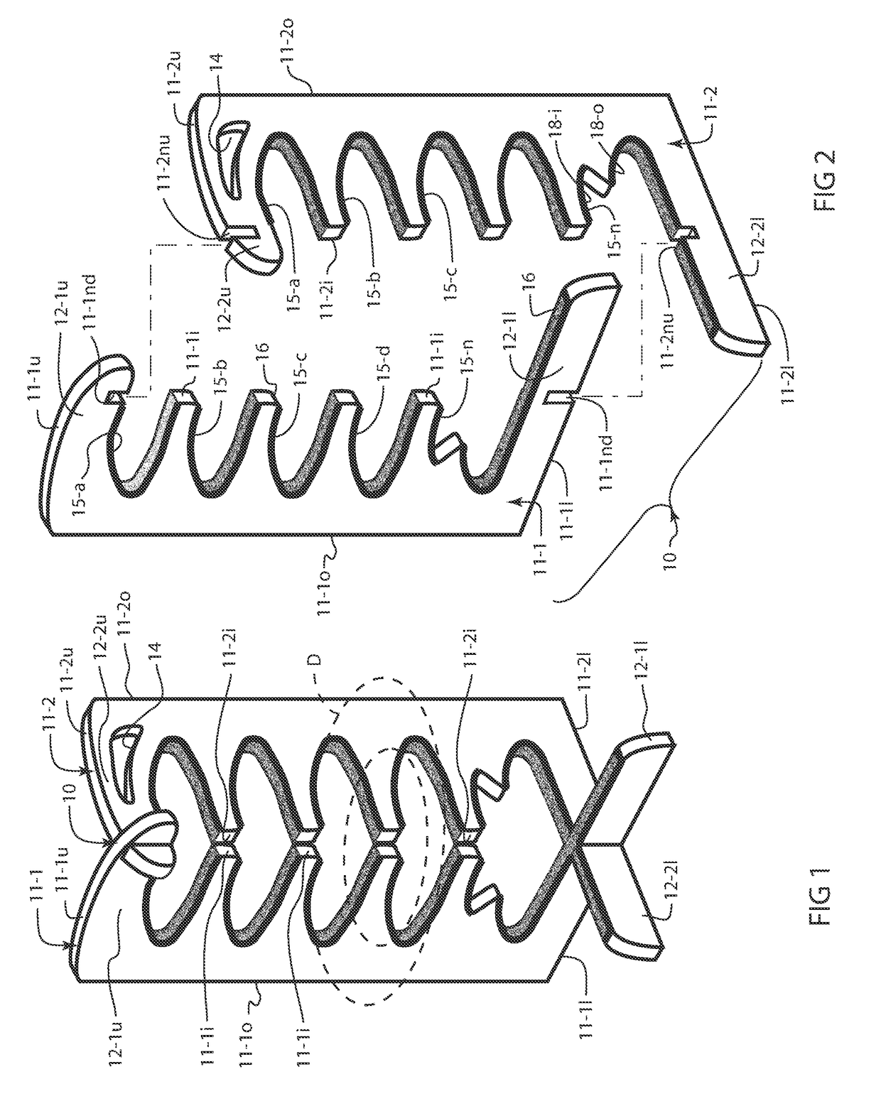
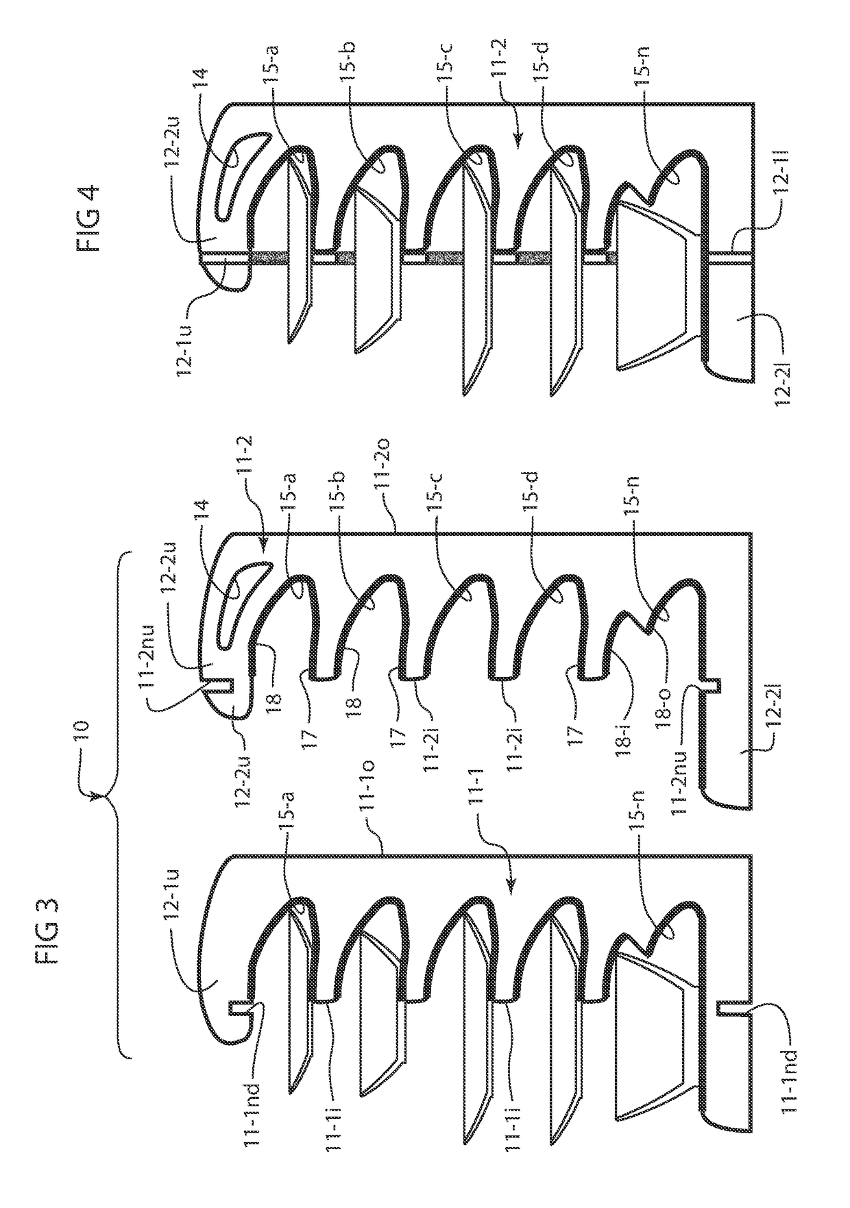
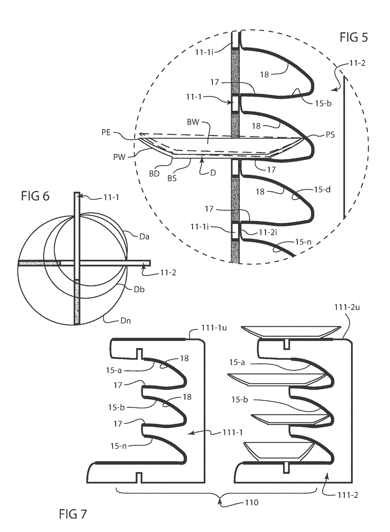
[0071]As shown in FIGS. 1-6 the first implementation of the inventive dish carrier assembly, generally designated by the numeral 10, comprises a pair of substantially similar generally planar panels which by their substantial similarity shall be designated herein by the trailing numerals 1 and 2, where the respective panels 11-1 and 11-2 are each of an elongate, generally rectangular planform respectively defined by inner and outer longitudinal edges 11-1i and 11-1o and 11-2i and 11-2o. Transversely an upper and a lower edge 11-1u and 11-1l and 11-2u and 11-2l limit the planform of the respective panels 11-1 and 11-2, each of the upper and lower edges extending beyond the corresponding inner edges 11-1i and 11-2i to continue as the exterior edges of corresponding upper and a lower planar extensions 12-1u and 12-1l and 12-2u and 12-2l, with the lower extensions 12-1l and 12-2l on each panel being greater in width and spanning further from the corresponding inner edges 11-1i and 11-2i...


PUM


Abstract

A dish assembly includes a pair of folding panels and a support platform. A bottom of the pair of folding panels are retained in the support platform. Each pair of folding panels includes a first vertical member and a second vertical member. At least one slot opening is formed in each vertical member. At least one slot opening is formed in the first and second vertical member. Each slot opening has an upper curved surface and a stability straight lower surface. The upper curved surface has at least a portion of which is a segment of an arc. The upper curved surface is located opposite the substantially straight lower surface. The upper curved surface having a height from a top end therefore to the substantially straight lower surface.

Description

CROSS-REFERENCES TO RELATED APPLICATIONS[0001]This is a continuation-in-part application, which takes priority from continuation-in-part patent application Ser. No. 14 / 718,081 filed on May 21, 2015, which takes priority from patent application Ser. No. 14 / 470,878 filed on Aug. 27, 2014, issued on Jul. 28, 2015 with U.S. Pat. No. 9,089,231, which was a continuation-in-part of U.S. patent application Ser. No. 13 / 946,769 filed on Jul. 19, 2013, issued on Sep. 30, 2014 with U.S. Pat. No. 8,844,733, which was a continuation-in-part of U.S. patent application Ser. No. 13 / 134,636 filed on Jun. 13, 2011, issued on Sep. 24, 2013 with U.S. Pat. No. 8,540,084, which in turn is a continuation-in-part of U.S. patent application Ser. No. 13 / 065,175 filed on Mar. 16, 2011, issued on Sep. 24, 2013 as U.S. Pat. No. 8,540,083, which, in turn, obtains the benefit of the earlier filing date of U.S. Provisional Patent Application No. 61 / 341,874 filed on Apr. 6, 2010, and the benefit of these earlier dat...

Claims


Application Information

Patent Timeline
Patent Type & Authority Patents(United States)
IPC IPC(8): A47G19/00A47F10/06A47B81/04A47B43/00A47J47/16A47G19/08A47F7/00
CPCA47G19/08A47B81/04A47F7/0007A47F7/0064A47F10/06A47J47/16A47F7/0071A47B2230/0085A47B43/00
Inventor WAKSUL, ISAAC J.
Owner WAKSUL ISAAC J
Why Eureka
Try Eureka