Downshift techniques for oscillator with feedback loop

a feedback loop and oscillator technology, applied in the field of clocking circuitry, can solve the problems of affecting the operation of the oscillator, the error of circuitry on a critical path, and the inability of the pll clock source to change the frequency rapidly, so as to facilitate voltage recovery, reduce switching power consumption, and accelerate the downshifting of the oscillator output frequency

Active Publication Date: 2019-03-12
APPLE INC
View PDF10 Cites 2 Cited by
  • Summary
  • Abstract
  • Description
  • Claims
  • Application Information

AI Technical Summary

Benefits of technology

[0006]In various embodiments, the disclosed techniques may allow for rapid downshifting of oscillator output frequency, which may reduce switching power consumption, facilitate voltage recovery before critical path failure, prevent errors, prevent circuit damage, etc.

Problems solved by technology

Computing devices (especially mobile devices) sometimes experience rapid current increases (e.g., when multiple components begin operating at the same time during a burst of activity).
This may cause a drop in voltage supply which may in turn cause errors in circuitry on a critical path, absent some preventative measure.
Because of the nature of the feedback loop, however, PLL clock sources are typically unable to change frequency rapidly.
The nature of a negative feedback loop may render rapid frequency changes difficult, e.g., because of corrections by the loop.

Method used


Image

  • Downshift techniques for oscillator with feedback loop
  • Downshift techniques for oscillator with feedback loop
  • Downshift techniques for oscillator with feedback loop

Examples


Embodiment Construction

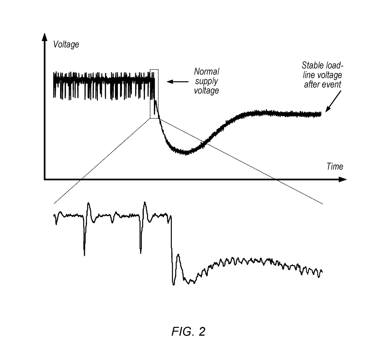
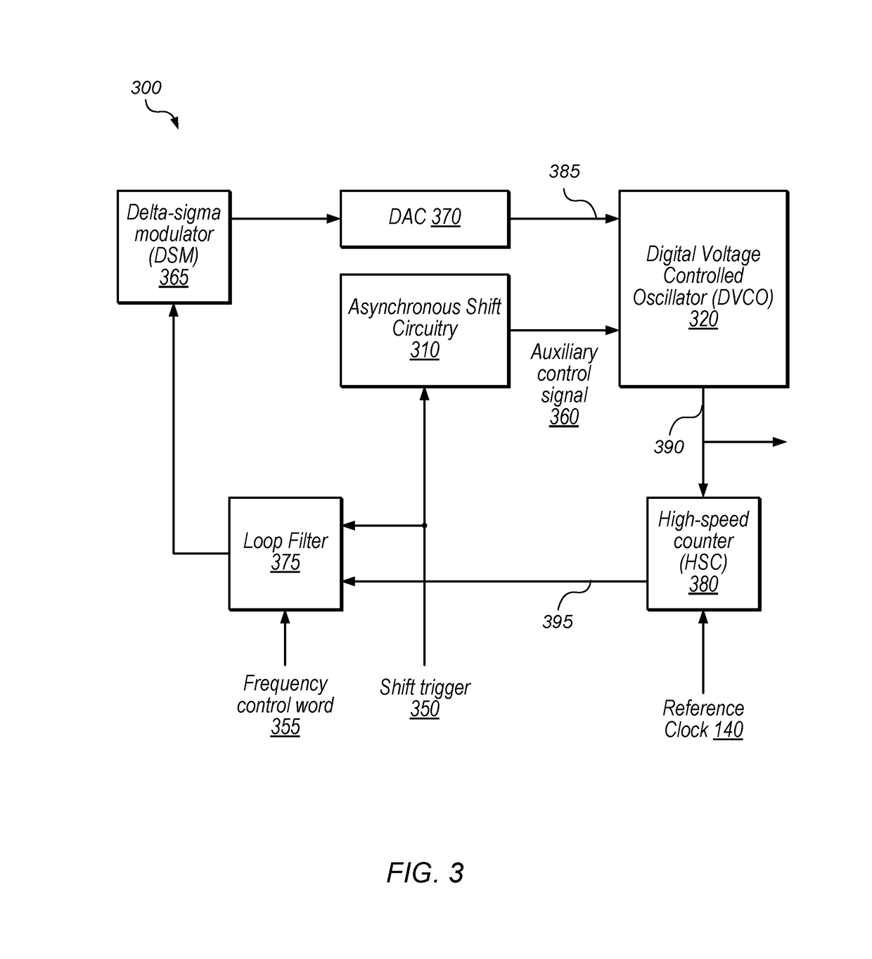
[0021]This disclosure initially describes, with reference to FIGS. 1A-1B, general embodiments of a feedback-controlled oscillator with open and closed-loop modes of operation for rapid downshift. FIG. 2 shows an exemplary plot of supply voltage during a current step event. More detailed embodiments and downshift techniques are discussed with reference to FIGS. 3-6. FIG. 7 shows an exemplary device and FIG. 8 shows an exemplary computer-readable medium. In some embodiments, the disclosed techniques allow for rapid downshifting of oscillator output frequency, which may reduce switching power consumption, facilitate voltage recovery, prevent errors, prevent circuit damage, etc.

Exemplary Clock Source with Rapid Downshift

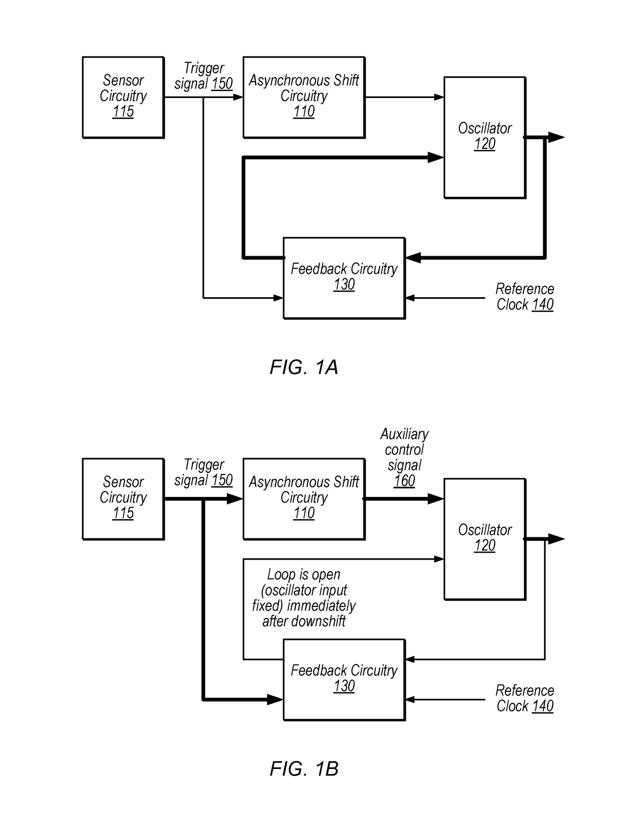
[0022]FIGS. 1A and 1B are block diagrams illustrating an exemplary device with a clock source capable of frequency downshift from a first frequency to a second, lower frequency, according to some embodiments. In some embodiments, this frequency downshift occurs rapidly i...


PUM


Abstract

Techniques are disclosed relating to rapidly downshifting the output frequency of an oscillator. In some embodiments, the oscillator is configured to operate in a closed-loop mode in which negative feedback is used to maintain a particular output frequency (e.g., in a phase-locked loop (PLL)). In some embodiments, the negative feedback loop is configured to maintain the output of the oscillator at a particular frequency based on a reference clock signal and the output of the oscillator. The nature of a negative feedback loop may render rapid frequency changes difficult, e.g., because of corrections by the loop. Therefore, in some embodiments, the loop is configured to switch to an open-loop mode in which a control input to the oscillator is fixed. In some embodiments, the loop switches to open-loop mode in response to a trigger signal and control circuitry forces the oscillator to a new target frequency.

Description

BACKGROUNDTechnical Field[0001]This disclosure relates generally to clocking circuitry and more specifically to frequency downshift for feedback-controlled oscillators.Description of the Related Art[0002]Computing devices (especially mobile devices) sometimes experience rapid current increases (e.g., when multiple components begin operating at the same time during a burst of activity). This may cause a drop in voltage supply which may in turn cause errors in circuitry on a critical path, absent some preventative measure. Extending cycle times during such intervals may be advantageous to enable a device to recover from a current step and corresponding voltage drop. Such an adjustment may need to be performed quickly to avoid critical path errors.[0003]Phase-locked loops are one type of circuitry used to generate clocking signals. In typical implementations, the output of a voltage-controlled oscillator (VCO) is compared with a reference signal to control the VCO in a feedback loop. T...

Claims


Application Information

Patent Timeline
Patent Type & Authority Patents(United States)
IPC IPC(8): H03L7/093H03B1/00H03L7/08H03L7/085H03L7/099
CPCH03L7/093H03B1/00H03L7/085H03L7/099H03L7/08H03L2207/06
Inventor LEIBOWITZ, BRIAN S.ZERBE, JARED L.PANT, SANJAY
Owner APPLE INC
Why Eureka
Try Eureka