Control device for automatic transmission

a control device and automatic transmission technology, applied in the direction of instruments, mechanical devices, digital data processing details, etc., can solve the problems of unfavorable sports driving lack of responsiveness, and achieve the effect of large engine brake for

Inactive Publication Date: 2009-07-02
AISIN AW CO LTD
View PDF17 Cites 17 Cited by
  • Summary
  • Abstract
  • Description
  • Claims
  • Application Information

AI Technical Summary

Benefits of technology

[0005]However, in order to obtain a large engine brake force, for example, during downhill driving or hard braking with the automatic transmission provided with the finely spaced (multi-speed) gear ratios (shift speeds) such as described above, it is required to change the gear ratio (shift speed) through, for example, two or three stages. P

Problems solved by technology

Particularly, in the case of performing the manual shift operation as described above, there has been a problem in that the driver needs to successively perform a manual shift operation a multiple number of times in a short period of time, resulting in a troublesome operation that is not preferable in terms of ease of operation of the vehicle.
However, when taking into account the time for the long pressing required for judgment to prevent an erroneous operation from occurring, a long time

Method used


Image

  • Control device for automatic transmission
  • Control device for automatic transmission
  • Control device for automatic transmission

Examples


first embodiment

[0053]First, a description will be made of a first embodiment that takes into account the road gradient serving as a road condition, according to FIGS. 4 and 5, with reference to FIG. 1.

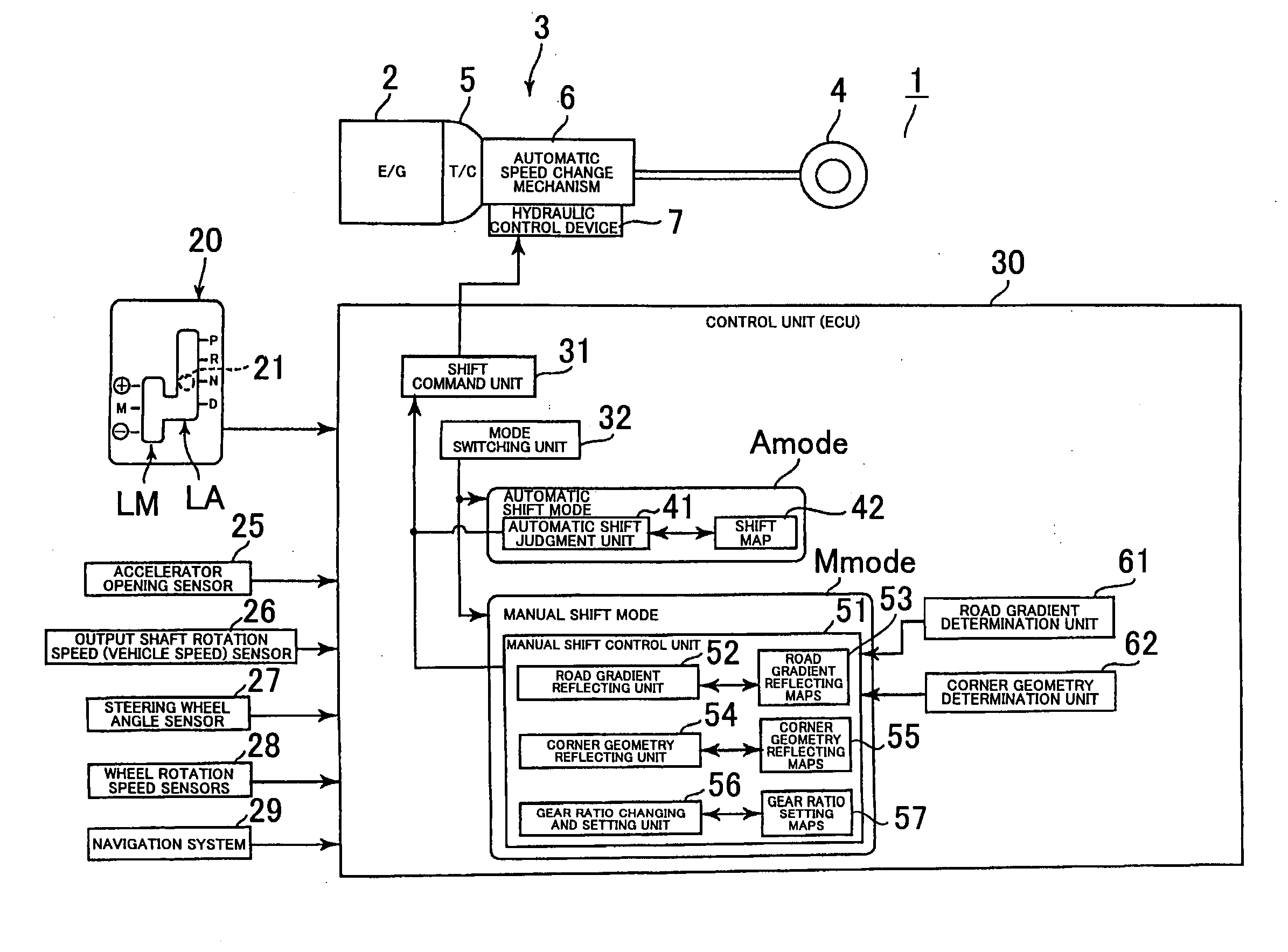
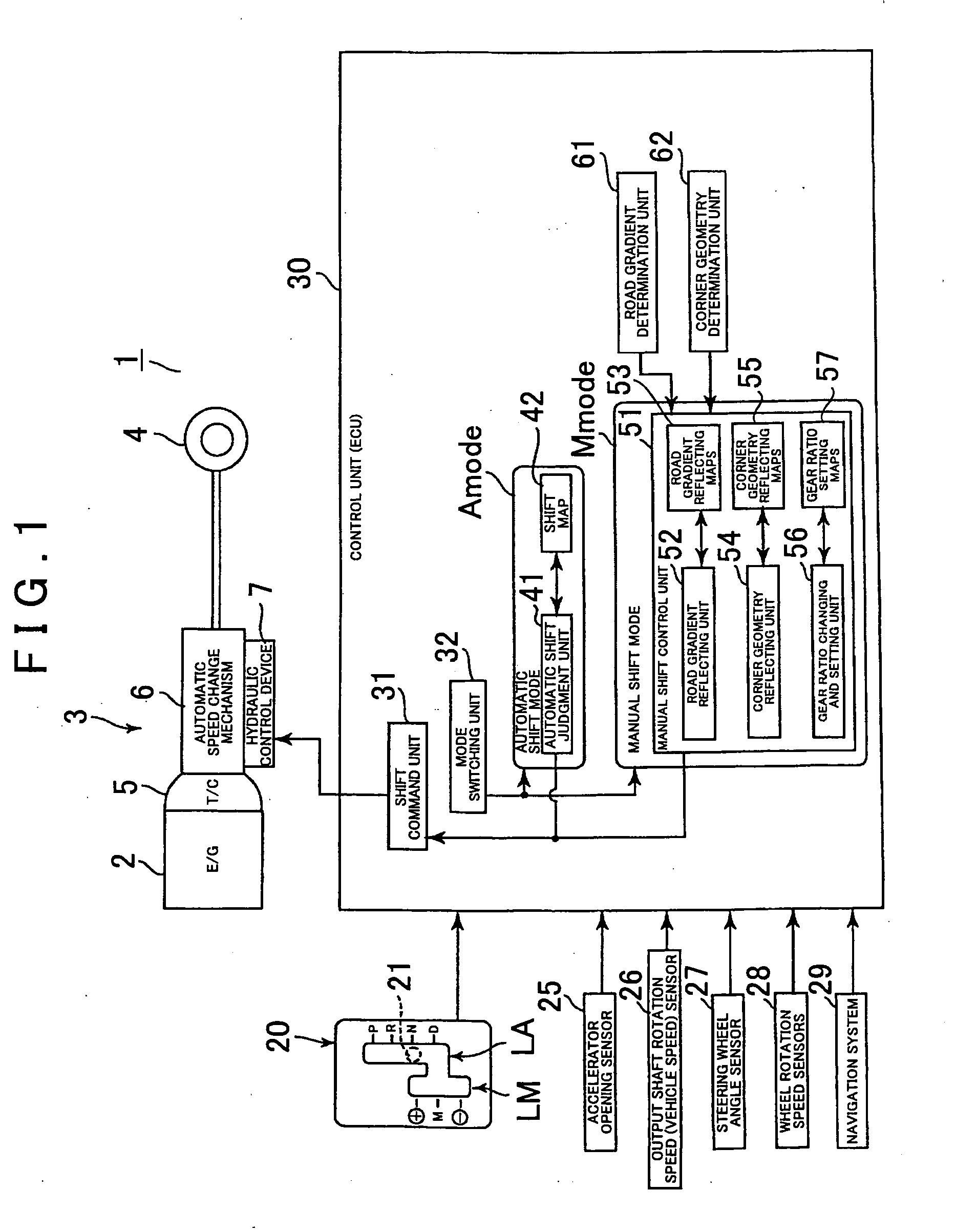
[0054]For example, in the state in which an ignition switch is turned on (at least in the state of the manual shift mode Mmode), the road gradient determination unit 61 calculates the running resistance of the vehicle as needed, based on the accelerator opening TH detected by the accelerator opening sensor 25 and on the vehicle speed V detected by the output shaft rotation speed (vehicle speed) sensor 26, and based on the running resistance, determines the gradient value of the road on which the vehicle is currently running as needed. Note that the road gradient determination unit 61 may determine the road gradient, for example, based on the road information from a navigation system 29 in the case of a vehicle equipped with the navigation system 29, or may determine the road gradient, for example, by...

second embodiment

[0071]Next, description will be made of a second embodiment that takes into account the road gradient by correcting the shift speed after downshift based on the road gradient serving as a road condition, according to FIG. 6, with reference to FIG. 1.

[0072]In the same way as the first embodiment described above, for example, when the driver has operated the shift lever 21 from position “D” to position “M”, control according to the second embodiment is started. For example, if the manual downshift operation is performed while the vehicle is running on the level road (S2-1), the gear ratio changing and setting unit 56 first sets the shift speed (gear stage) to which the manual downshift is to be made, according to another logic that is different from the determination of shift speed based on the road gradient described in the above-described first embodiment, by, for example, referring to the gear ratio setting maps 57 (S2-2).

[0073]Note that the another logic can be a logic, for exampl...

third embodiment

[0082]Next, description will be made of a third embodiment that takes into account the corner geometry serving as a road condition, according to FIGS. 7 and 8, with reference to FIG. 1.

[0083]For example, in the state in which an ignition switch is turned on (at least in the state of the manual shift mode Mmode), the corner geometry determination unit 62 determines the steering angle (that is, the corner geometry of the road on which the vehicle is currently running) as needed, based on the rotation angle of the steering wheel (not shown) detected by the steering wheel angle sensor 27. Note that the corner geometry determination unit 62 may determine the steering angle (that is, the corner geometry) by detecting the respective rotation speeds of the front, rear, right, and left wheels with the wheel rotation speed sensors 28, and then based on the difference among those rotation speeds (particularly, the difference in rotation speed between the front right wheel and the rear left whe...


PUM


Abstract

A control device for an automatic transmission capable of operating in an automatic shift mode in which a gear ratio is automatically selected based on driving conditions of a vehicle, and also capable of operating in a manual shift mode in which the gear ratio is changed based on an upshift command or a downshift command by manual operation of a manual operation device, the control device includes a manual shift control unit that changes and sets the gear ratio after downshift depending on road conditions when the downshift command has been operated by the manual operation device in the manual shift mode, and performs the downshift to the gear ratio that has been changed and set.

Description

INCORPORATION BY REFERENCE[0001]The disclosure of Japanese Patent Application No. 2007-338148 filed on Dec. 27, 2007 including the specification, drawings and abstract is incorporated herein by reference in its entirety.BACKGROUND[0002]The present invention relates to a control device and method for an automatic transmission.[0003]An automatic transmission mounted on a vehicle or the like is structured so as to be capable of driving the vehicle at an appropriate gear ratio without a shift operation by a driver, by automatically judging a gear ratio (shift speed) based on an accelerator opening and a vehicle speed particularly during forward driving. However, in recent years, in order to meet such a demand for sports driving and a delicate selection of engine braking for example, automatic transmissions have been proposed that also allow a so-called manual shift operation in which the driver can select a gear ratio (shift speed) (see, for example, Japanese Patent Application Publicat...

Claims


Application Information

Patent Timeline
IPC IPC(8): B60W10/10F16H61/26F16H59/10F16H59/66F16H61/04F16H61/21F16H61/68F16H61/684F16H61/686
CPCF16H59/66F16H61/0213Y10T477/69367F16H2059/663F16H61/0248
Inventor SUGIURA, TADASHITAKEI, YOSUKEOGASAWARA, HIDEAKITSUTSUI, HIROSHI
Owner AISIN AW CO LTD
Why Eureka
Try Eureka