Eureka AIR delivers breakthrough ideas for toughest innovation challenges, trusted by R&D personnel around the world.

Gas turbine blade array with reduced acoustic output

a technology of acoustic output and a turbine blade array, which is applied in the direction of machines/engines, liquid fuel engines, mechanical equipment, etc., can solve the problems of effective decay in the inlet, decay-prone harmonics, and forward-directed noise travel of noise, and achieve the effect of reducing the noise generated by the combination of rotors

Active Publication Date: 2019-03-19
RTX CORP
View PDF7 Cites 0 Cited by
  • Summary
  • Abstract
  • Description
  • Claims
  • Application Information

AI Technical Summary

Benefits of technology

[0016]In accordance with another aspect of the present disclosure, a method of reducing combination tone noise in a rotor of a gas turbine engine is disclosed. The method may include, distributing a plurality of blades about a rotor disk of the rotor such that the blades generate a decay-resistant harmonic.
[0022]In accordance with yet another aspect of the present disclosure, a method of mitigating combination tone noise generated by a rotor is disclosed. The method may include providing a rotor having a rotor disk and a plurality of blades. At least one blade may have a physical nonuniformity. The method may further include generating a decay-resistant harmonic with a particular positioning of the blades of the rotor based on any nonuniformities of the blades.

Problems solved by technology

This combination tone noise travels in the forward direction out of the inlet and may be undesirable to people in a cabin of an aircraft utilizing the engine and in a community around the aircraft.
While effective, new engine designs may generate decay-prone harmonics too closely to a lip of the inlet of the nacelle to effectively decay in the inlet.
Further, active methods of noise reduction require moving components and / or electricity.
Such components are maintenance intensive and any electricity usage drains output from the engine.

Method used


Image

  • Gas turbine blade array with reduced acoustic output
  • Gas turbine blade array with reduced acoustic output
  • Gas turbine blade array with reduced acoustic output

Examples


Embodiment Construction

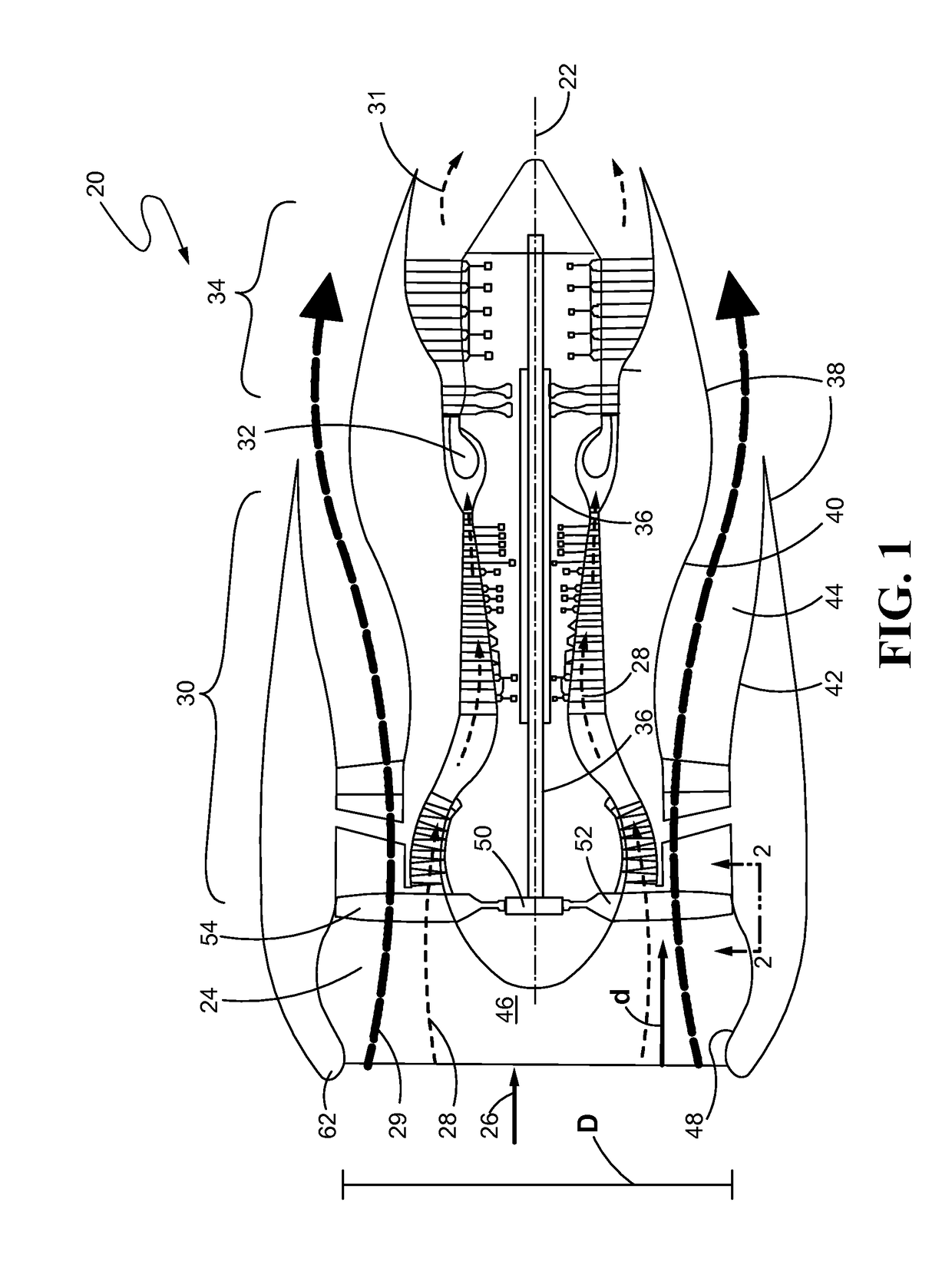
[0034]Referring now to the drawings, and with specific reference to FIG. 1, a gas turbine engine 20 is illustrated. As can be seen, the engine 20 includes a plurality of components axially aligned along a central axis 22. At a forward end of the engine 20 a fan 24 rotates to draw in and pressurize ambient air 26. This air is split into a core flow 28 and a bypass flow 29. The core flow 28 flows to a compressor section 30 where it is further compressed. From the compressor section 30, the compressed core flow 28 travels to a combustor 32 where the core flow 28 is mixed with a fuel and combusted to form an exhaust 31. The exhaust 31 expands through a turbine section 34 and exits the engine 20 at an aft end. As the exhaust 31 expands, it rotates turbines of the turbine section 34. This rotational motion is communicated to the fan 24 and compressor section 30 via an engine shaft 36, or plurality of engine shafts 36 in the case of a dual-spool engine 20 as shown.

[0035]A nacelle 38 typica...


PUM


Abstract

In accordance with one aspect of the disclosure, a rotor for a gas turbine engine is disclosed. The rotor may include a rotor disk and a plurality of blade extending radially outward from the rotor disk. At least one of the blades may have a physical nonuniformity. The blades may be distributed about the rotor disk based on any physical nonuniformities of the blades to generate at least one decay-resistant harmonic.

Description

CROSS-REFERENCE TO RELATED APPLICATIONS[0001]This patent application is a 35 USC § 371 U.S. national stage filing of International Patent Application No. PCT / US13 / 75946 filed on Dec. 18, 2013, which claims priority under the 35 USC § 119(e) to U.S. Provisional Patent Application Ser. No. 61 / 787,535, filed on Mar. 15, 2013.FIELD OF THE DISCLOSURE[0002]The present disclosure generally relates to gas turbine engines and, more specifically, relates to noise reduction configurations for fans of gas turbine engines.BACKGROUND OF THE DISCLOSURE[0003]Gas turbine engines generally have a plurality of axially aligned components including a fan, a compressor section, a combustor, and a turbine section. The fan, positioned at a forward end of the engine, rotates to draw in and pressurize ambient air. Some of the accelerated air flows to the compressor section, as a core flow, where the air is compressed and then flows to the combustor. At the combustor, the compressed air is mixed with fuel and...

Claims


Application Information

Patent Timeline
Patent Type & Authority Patents(United States)
IPC IPC(8): F04D29/66F01D5/14F04D29/32F01D5/06F01D5/10
CPCF04D29/666F01D5/06F01D5/10F01D5/145F04D29/321Y02T50/673F05D2220/36F05D2260/961Y02T50/671Y02T50/60
Inventor TOPOL, DAVID A.PRASAD, DILIP
Owner RTX CORP
Why Eureka
Eureka Blog
Learn More