Optical waveguide with a reflective pattern for propagating a light beam

Active Publication Date: 2019-03-19
VALEO VISION SA
View PDF84 Cites 0 Cited by
  • Summary
  • Abstract
  • Description
  • Claims
  • Application Information

AI Technical Summary

Benefits of technology

The invention proposes a new way to design lighting devices for motor vehicles using an optical waveguide that can create both uniform and anisotropic illumination. This allows for the creation of curved and inclined devices. The invention also uses a reflective pattern that includes three different portions to achieve double reflection. A coating is applied to the waveguide to recover light and direct it in the desired direction. This technology is easy and inexpensive to implement.

Problems solved by technology

However, if the described solutions are adapted in particular for the production of phototherapy appliances or to provide backlighting for a display screen, they would not then be suitable for the production of curved optical waveguides for automobile lighting and / or signalling devices, which guides are in addition inclined in relation to the frontal plane perpendicular to the optical axis of the device, that is to say to a vertical plane, the optical axis being substantially parallel to the horizontal, and which moreover would meet the mandatory photometric standards.

Method used


Image

  • Optical waveguide with a reflective pattern for propagating a light beam
  • Optical waveguide with a reflective pattern for propagating a light beam
  • Optical waveguide with a reflective pattern for propagating a light beam

Examples


Embodiment Construction

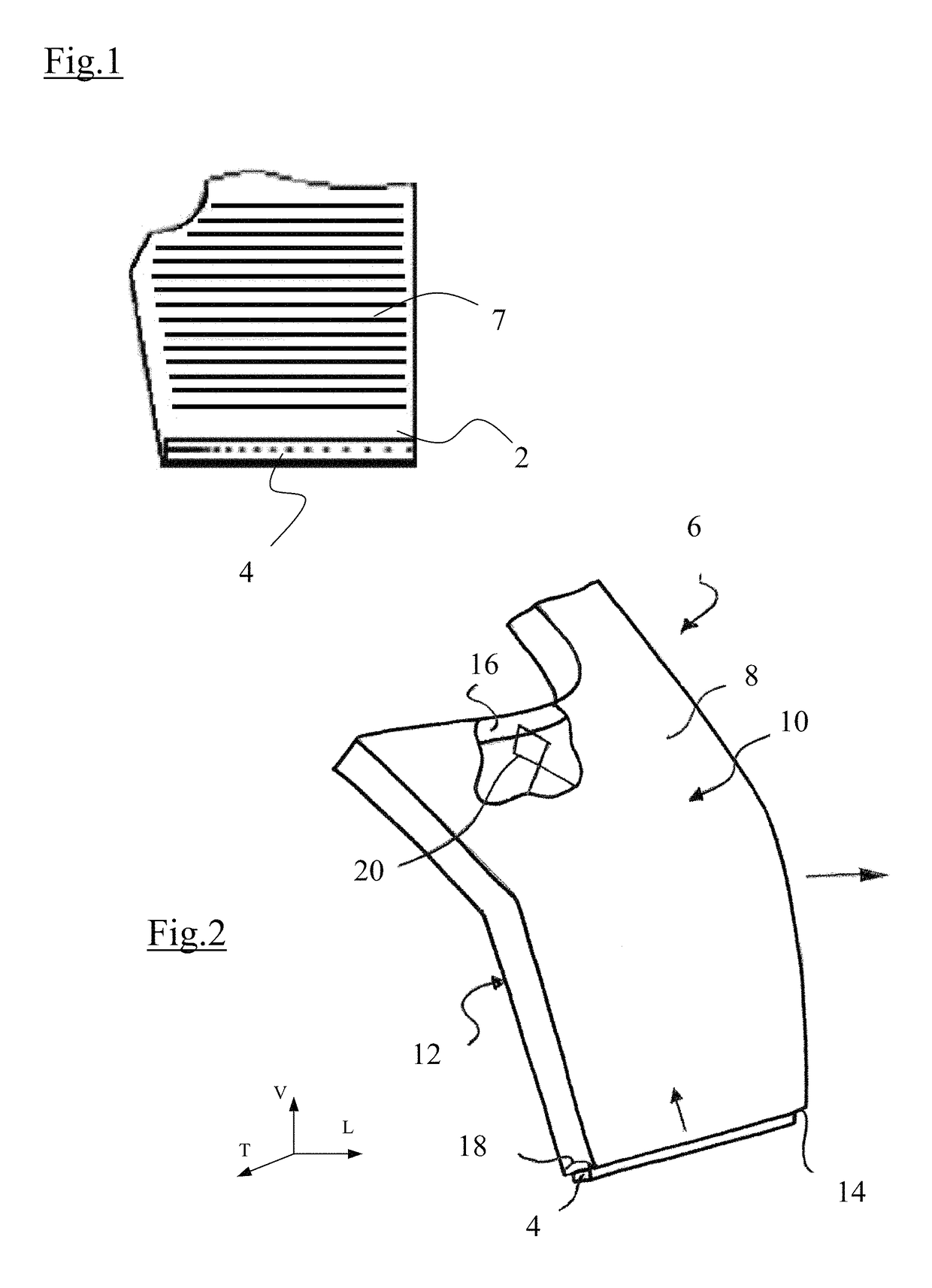
[0035]The expression “longitudinal direction” L is used below to denote the direction of driving of the automotive vehicle, and “transverse direction” T to denote a direction that is horizontal and perpendicular to the longitudinal direction. The vertical direction V designates the direction perpendicular to the two preceding directions, which also define a horizontal plane. The trihedron L,V,T is placed on certain figures for ease of reading.

[0036]A lighting and signaling device is represented in FIG. 1. In this case, this is a headlight of a motor vehicle which includes a cover lens 2 and which likewise includes a light source 4.

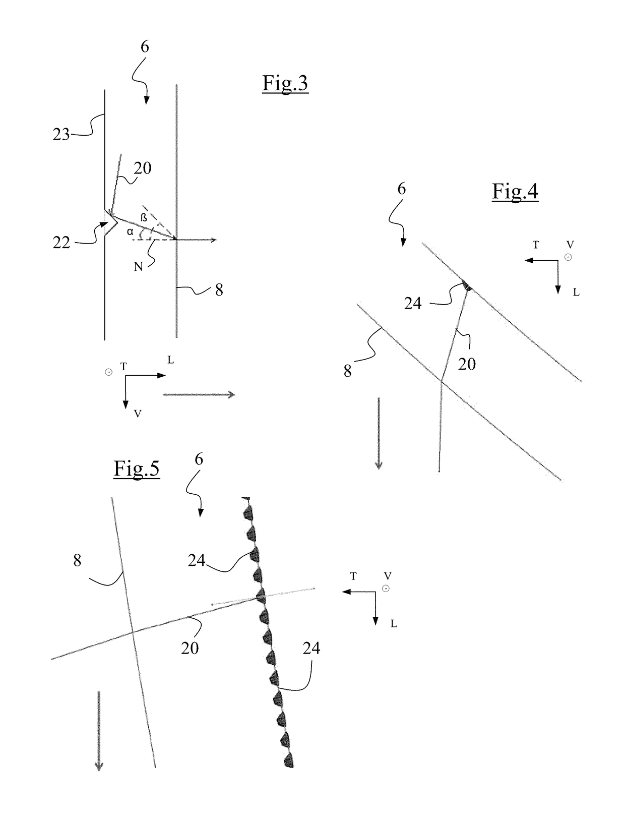
[0037]The light source 4 emits a light beam 20 in the interior of the headlight and an optical waveguide 6 is disposed in the interior of the headlight in order to receive and propagate the light beam 20 to an output face 8 of the optical waveguide 6 situated facing towards the cover lens 2. The optical waveguide 6 is configured with the aim of following t...


PUM


Abstract

An optical waveguide for the propagation of a light beam adapted to travel by successive total reflections off the faces of the waveguide to an output face where the light beam is refracted. One of the faces of the waveguide forms, facing towards the output face, a support face for a pattern extending across the main direction of the beam to divert same towards the output face. According to a characterizing feature of the invention, the pattern is a bifunctional reflective pattern that is integral with the support face, having three portions including end portions formed by cone portions between which there is interposed an intermediate portion that comprises two facets that meet at a top edge, which is not parallel to the support face for the patterns.

Description

CROSS-REFERENCE TO RELATED APPLICATIONS[0001]This application is the U.S. National Phase application of PCT Application No. PCT / EP2014 / 060479 filed May 21, 2014, which claims priority to the French application 1354570 filed on May 22, 2013, which applications are incorporated herein by reference and made a part hereof.BACKGROUND OF THE INVENTION1. Field of the Invention[0002]The present invention relates to an optical waveguide and its use in a lighting device equipping a motor vehicle, in particular an automotive vehicle.2. Description of the Related Art[0003]The use of optical waveguides is becoming increasingly common in the field of automotive vehicle lighting and signalling. In fact, these have the advantage of being able to adopt highly varied geometric forms and to create an illuminating surface even in less accessible regions of the lighting and / or signalling device. This is particularly beneficial in the present context, where the designers of motor vehicles are seeking to ...

Claims


Application Information

Patent Timeline
IPC IPC(8): F21V8/00F21S41/24F21S43/239F21S43/245
CPCF21S41/24F21S43/239F21S43/245G02B6/0038G02B6/0036G02B6/0061G02B6/0043G02B6/0055
Inventor GERMON, FRANCOISDOHA, JEAN-FRANCOISSAGNA, BOUBACAR
Owner VALEO VISION SA
Why Eureka
Try Eureka