Evaluation of signals of fluorescence scanning microscopy using a confocal laser scanning microscope

a fluorescence scanning microscopy and laser scanning microscope technology, applied in the field of evaluating signals of fluorescence scanning microscopy, can solve the problems of not changing the “waste” of out-of-focus photons, increasing the intensity of excitation light, and not being suitable for florescence measuremen

Active Publication Date: 2019-03-19
CARL ZEISS MICROSCOPY GMBH +1
View PDF10 Cites 0 Cited by
  • Summary
  • Abstract
  • Description
  • Claims
  • Application Information

AI Technical Summary

Benefits of technology

[0033]Therefore, it is an object of the invention to provide a possibility for evaluating signals of fluorescence scanning microscopy with a high resolution and depth discrimination (known as sectioning) comparable to that of a confocal microscope without the loss of a large number of fluorescence photons at the confocal aperture (pinhole) when using a confocal fluorescence scanning microscope (e.g., according to DE 10 2014 002 328) in which, by means of diffractive optics for splitting into bundles, there is impressed on the bundles in every diffraction order a spherical phase differing from the other diffraction orders, the wavefronts from different focal planes, which wavefronts are accordingly differently curved, are split into different diffraction orders and are detected exclusively on the illumination wavelength. In other words, signals arriving (axially) in parallel in Z direction from blurrily imaged planes are not filtered out through (real or virtual) confocal pinholes but rather contribute to the wanted signal of the sharply (confocally) imaged plane.
[0045]In this regard, it turns out to be advantageous that the spreading out of the focal planes and an increased resolution in the measuring volume depth can be selectively adjusted in that the elongated focus is adjusted by means of a zoom objective between the sample and the diffractive optics.
[0046]The elongated focus can advantageously be adjusted by underfilling the entrance pupil of the microscope objective. In this regard, an additional correlation of fluorescence signals scanned in lateral planes of the sample with increased lateral resolution is achieved to supplement the correlation of fluorescence signals in depth with elongated focus which is expanded by underfilling the entrance pupil of the microscope objective.
[0052]In both cases, it proves advantageous that zoom optics for underfilling the entrance pupil of the microscope objective are provided in order to further spread apart the distances of the focal planes.
[0057]The intended goals of: (a) reducing photodamage of samples; and (b) reducing capture times for given 3D volumes (i.e., for thick samples), can only be realized in that the radiated output is virtually constant in all focal planes such that the fluorescence generated therefrom need only be evaluated simultaneously in all focal planes. This is in turn only possible when signal components which do not originate from the primary focal plane are admitted for signal capture and are subsequently correctly associated with the focal planes. This problem is solved according to the invention through correlation of the signals from the detector regions. Since different emitters blink (i.e., have different fluctuations in the emission characteristic) independently from one another stochastically, it is possible to associate correlating fluorescence signals of adjacent detector regions with a determined emitter. This is the case for virtually all emitters, although the mechanisms and, therefore, the time scales of the fluctuations differ for different planes, so that the fluorescence emitters in the different planes have an uncorrelated emission behavior in direction of the optical axis by means of which they can be separated subsequently.

Problems solved by technology

Further, the known advantages of laser scanning microscopy (confocal microscopy) such as optical sectioning (suppression of out-of-focus signals) and high flexibility are accompanied by disadvantages and limitations:1) expenditure of time on sequential data acquisition;2) damage to sample (e.g., bleaching) through high intensity in the focus; and3) damage to sample (e.g., bleaching) through unused out-of-focus intensity.
The simplest solution for both of the above-mentioned aims a) and b), which would consist in increasing the intensity of the excitation light is not feasible as a singular approach because it is accompanied by an unwanted bleaching of the sample.
However, nothing changes with respect to the “waste” of out-of-focus photons (third disadvantage).
This last aspect—apart from the unwanted stress on the sample—represents a fundamental limitation of the confocal method in that many planes of the sample are illuminated but are not evaluated although the integrated excitation output is the same in every plane.
All of the wavelengths except that of the illumination light are then discriminated with a confocal aperture, so this multifocal imaging variant is not suitable for florescence measurements (because of Stokes shift and the spectral bandwidth of the florescence emission).
However, to date, SOFI has only been able to be demonstrated for specific fluorescence systems because the time scales within which the triplet OFF state occurs are much too short even for the fastest available continuous-operation area detectors (CMOS, CCD).
Therefore, SOFI and dSTORM methods are not suitable for the broad application of common fluorescent dyes.
For this reason, however, it is to be expected as disadvantageous that the detection is in no way more light-efficient than in the sequential mode of sectioning with confocal fluorescence microscope.
However, in real measurements, an individual luminescent particle is virtually never assumed so that, in real samples, the signals from planes which are offset in the direction of the optical axis are superposed on one another on the sensor segments and, in case of a sample structure which is unknown a priori, can no longer be unequivocally associated with the planes because there is substantial crosstalk of signals from “blurrily imaged” planes on the detectors for diffraction orders separated through the DOE system owing to the absence of a confocal discrimination of signals from different planes.

Method used


Image

  • Evaluation of signals of fluorescence scanning microscopy using a confocal laser scanning microscope
  • Evaluation of signals of fluorescence scanning microscopy using a confocal laser scanning microscope
  • Evaluation of signals of fluorescence scanning microscopy using a confocal laser scanning microscope

Examples


Embodiment Construction

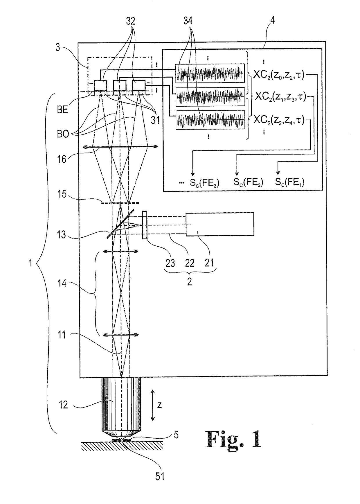
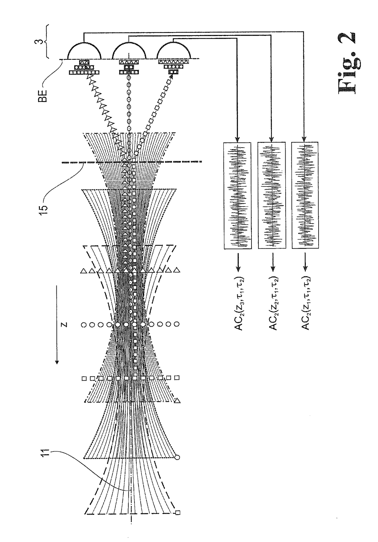
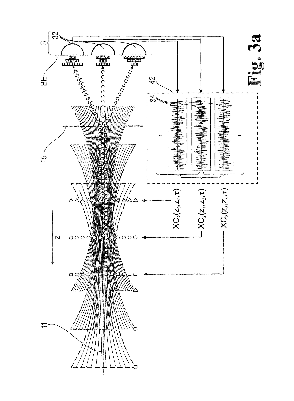
[0068]The basic flow of the method which can be perceived based on a confocal laser scanning microscope shown schematically in FIG. 1 and which has as subject matter the evaluation of signals of fluorescence scanning microscopy with simultaneous excitation and detection of fluorescence in different focal planes FE of a sample 5 includes the following steps.

[0069]At least one illumination beam 22 is coupled by means of a beam combiner 12 into a microscope observation beam path 1 which is defined by a measuring volume 51 of the sample 5 up to an image plane BE and which has, along an optical axis 11, a microscope objective 12, the beam combiner 13 and a detector unit 3 arranged in the image plane BE.

[0070]Next, the illumination beam 22 is focused with the microscope objective 12 in the measuring volume 51, wherein the illumination beam 22 passes through a beam-forming phase mask 23 in an illumination pupil for generating an elongated focus.

[0071]Fluorescent light generated in the meas...


PUM

PropertyMeasurementUnit
timeaaaaaaaaaa
timeaaaaaaaaaa
timeaaaaaaaaaa

Abstract

A method for evaluating signals of fluorescence scanning microscopy with simultaneous excitation and detection of fluorescence in different focal planes of a sample by means of confocal laser scanning microscopy. The invention evaluates signals of fluorescence scanning microscopy without the signal losses usually taking place with a confocal aperture, by coupling an illumination beam into a microscope observation beam path which images a measuring volume on a detector array arranged in the image plane, focusing the illumination beam which passes through a beam-forming phase mask for generating an elongated focus in the measuring volume, collecting and collimating fluorescent light generated in the measuring volume and routing it to diffractive optics which split the light beams into different diffraction orders and impress a different spherical phase on the light beams, imaging the different diffraction orders on detector regions of the detector array so that fluorescent light from focal planes at different depths of the measuring volume are associated with different diffraction orders, and associating the fluorescence signals on which crosstalk is superposed from different focal planes of the measuring volume with defined focal planes by means of correlation-based association based on distinguishable blinking behavior of fluorescing dyes.

Description

RELATED APPLICATIONS[0001]The present application is a U.S. National Stage application of International PCT Application No. PCT / DE2016 / 100207 filed on May 9, 2016 which claims priority benefit of German Application No. DE 10 2015 107 367.6 filed on May 11, 2015, the contents of each are incorporated by reference in their entirety.FIELD OF THE INVENTION[0002]The invention is directed to a method for the evaluation of signals of fluorescence scanning microscopy with simultaneous excitation and detection of fluorescence in different focal planes of a sample by means of confocal laser scanning microscopy, in particular for increasing efficiency of fluorescence scanning microscopy of thick samples, and to a confocal laser scanning microscope (LSM) with simultaneous fluorescence from different focal planes.BACKGROUND OF THE INVENTION[0003]Diverse attempts to improve the efficiency of the evaluation of fluorescent samples are known in prior-art confocal fluorescence scanning microscopy, e....

Claims


Application Information

Patent Timeline
Patent Type & Authority Patents(United States)
IPC IPC(8): G02B21/00G01N21/64
CPCG02B21/0076G01N21/6458G02B21/008G02B21/006G01N21/6408
Inventor NOVIKAU, YAUHENIKALKBRENNER, THOMASANHUT, TIEMOSCHWEDT, DANIELWALD, MATTHIAS
Owner CARL ZEISS MICROSCOPY GMBH
Why Eureka
Try Eureka