Supercharge Your Innovation With Domain-Expert AI Agents!

Method and device for detecting a control method of an inverter

a control method and inverter technology, applied in the direction of electric generator control, dynamo-electric converter control, dynamo-electric gear control, etc., can solve the problems of inability to correct the determination of power loss, change in the power loss for an operating point, and inability to control the power loss of the line to the electric machine. , to achieve the effect of efficient manner

Active Publication Date: 2019-03-19
ROBERT BOSCH GMBH
View PDF8 Cites 0 Cited by
  • Summary
  • Abstract
  • Description
  • Claims
  • Application Information

AI Technical Summary

Benefits of technology

[0006]The aim of the present invention consists of providing a method and a device for detecting a control method of an inverter for supplying current to an electric machine having N phases, which enables a correct determination of the power loss at low costs a without requiring additional input signals for the inverter.
[0025]In a preferable manner, one of the methods mentioned above of one the devices mentioned above is used in order to monitor a torque or respectively an actual torque of the electric machine and / or in order to estimate an operating-point-dependent power loss of the electric machine according to a control method detected by means of the method or the device. As a result, the actual torque of the electric machine can be correctly calculated and monitored in a particularly efficient manner.

Problems solved by technology

The power loss consists of losses in the lines to the electric machine, losses in the electric machine, iron losses and frictional losses.
Other control methods namely cause a change in the power loss for an operating point possibly overlap in a working area extending over the rotational speed and the torque.
A correct determination of the power loss is not possible without knowledge of the control method of the electric machine and thus a reliable monitoring of the actual torque generated by the electric machine is also not possible.

Method used


Image

  • Method and device for detecting a control method of an inverter
  • Method and device for detecting a control method of an inverter
  • Method and device for detecting a control method of an inverter

Examples


Embodiment Construction

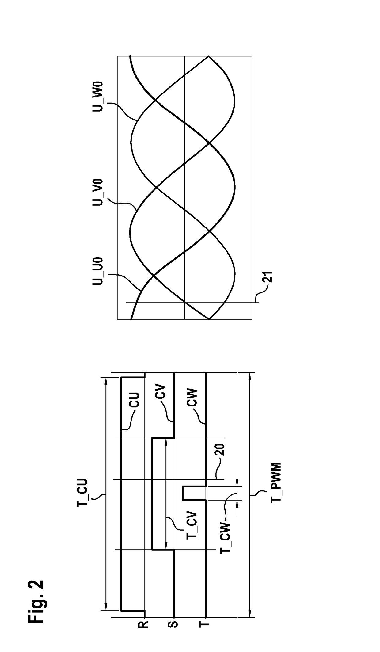
[0031]FIG. 1 illustrates a section of a system comprising an inverter 11 for supplying current to an electric machine 1, having N=3 phases U, V and W. The inverter 11 forms the direct current energy stored in a battery 2 in respective phase voltages U13 U0, U_V0 and U_W0 in order to feed said direct current energy as AC voltages via phase lines 12 to the electric machine 1. The inverter 11 is designed as a full bridge with an upper and a lower half bridge. For each of the three phases of the inverter 11, the AC voltage fed to the electric machine 1 is generated by means of a series circuit consisting of a parallel circuit of an IGBT 7U, 7V or 7W associated with the upper half bridge and a diode 8U, 8V or 8W and a parallel circuit of an IGBT 9U, 9V or 9W associated with the lower half bridge and a diode 10U, 10V or 10W. A control unit or respectively driver circuit 3 fed with control signals provides the power inverter or respectively inverter 11 with control signals CU, CV, CW (for ...


PUM


Abstract

The invention relates to a method for detecting a control method of an inverter (11) for supplying current to an electric machine (1), in particular a synchronous machine, having N phases. The method comprises sensing a control signal (CU, DU, CV, DV, CW, DW), which is fed to the inverter and which is clocked with a periodic cycle, over a specified number of periodic cycles of the control signal; determining a duty cycle frequency for the sensed control signal over the specified number of periodic cycles; and detecting the control method on the basis of the determined duty cycle frequency. The invention further relates to a device (5) designed to perform the method. In addition, the invention further relates a use of the method or of the device to monitor a torque of the electric machine and in particular to estimate an operating-point-dependent power loss of the electric machine according to the detected control method.

Description

[0001]The present invention relates to a method and a device for detecting a control method of an inverter for supplying current to an electric machine, in particular a synchronous machine, having N phases.[0002]A monitoring of an electric machine typical in practice is based on the fact that a target torque to be generated by the electric machine is compared with an actual torque generated by the electric machine. The actual torque is typically not directly measured but calculated from measurement variables. In order to monitor the correct operation of the inverter, it is required that these measurement values are not taken from a functional unit upstream of the inverter but from the inverter and downstream components thereof.[0003]The actual torque M_ist can be determined by means of a calculation of the mechanical power output P_mech as M_ist=P_mech / (2πn) prevailing on the shaft of the electric machine, wherein n is the rotational speed of the electric machine. The mechanical pow...

Claims


Application Information

Patent Timeline
Patent Type & Authority Patents(United States)
IPC IPC(8): H02P27/08G01R31/44G01R23/15H02P21/22G01R19/17H02P21/20G01R31/34H03K9/08
CPCH02P21/20G01R19/17G01R23/155G01R31/44H02P21/22H02P27/08G01R31/343H03K9/08
Inventor TATIYOSYAN, SEVAN
Owner ROBERT BOSCH GMBH
Features
  • R&D
  • Intellectual Property
  • Life Sciences
  • Materials
  • Tech Scout
  • Unparalleled Data Quality
  • Higher Quality Content
  • 60% Fewer Hallucinations
Learn More