Eureka AIR delivers breakthrough ideas for toughest innovation challenges, trusted by R&D personnel around the world.

Vibratory bowl feeder

a feeder and vibrating bowl technology, applied in the direction of conveyor parts, conveyors, jigging conveyors, etc., can solve the problems of surface damage and laborious process, and achieve the effect of reducing the impa

Active Publication Date: 2019-03-26
LINEAR GRP SERVICES LLC
View PDF9 Cites 4 Cited by
  • Summary
  • Abstract
  • Description
  • Claims
  • Application Information

AI Technical Summary

Benefits of technology

The improved vibratory bowl feeder has a removable impact cone made from a special thermoplastic that deflects falling industrial workpieces towards the bowl. The impact cone is secured to the bowl with a center bolt and an adhesive layer. The shape of the impact cone can be customized for different industrial workpieces. This allows for easy replacement and minimal downtime. The impact cone can also be used for other articles such as electronic subassemblies and pharmaceutical products.

Problems solved by technology

Over time, however, this surface can become damaged after repeated impacts from the falling workpieces.
This process is labor intensive and can require the vibratory bowl feeder to be taken off line for as much as one week while the damaged bowl is serviced.

Method used


Image

  • Vibratory bowl feeder
  • Vibratory bowl feeder
  • Vibratory bowl feeder

Examples


Embodiment Construction

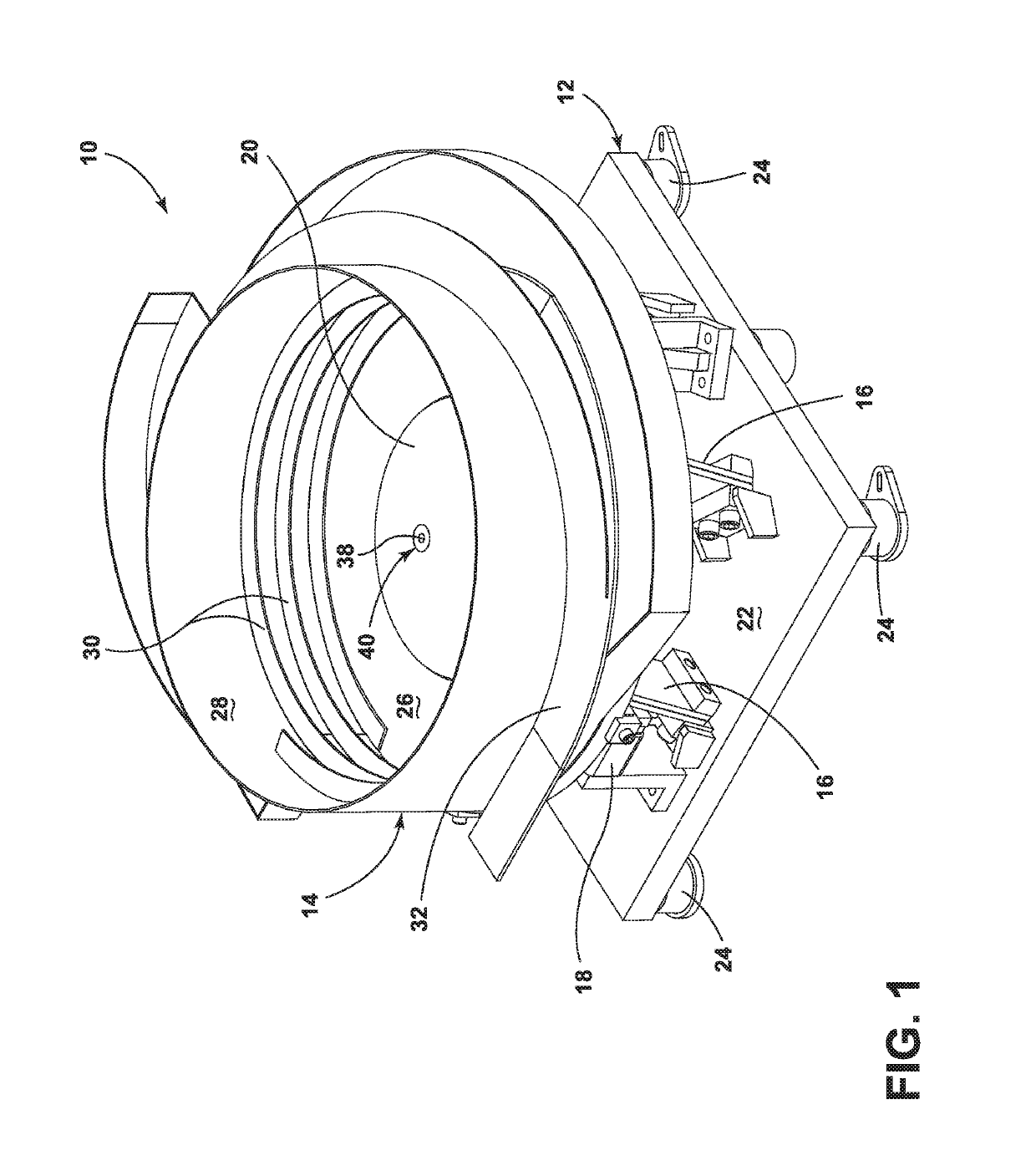
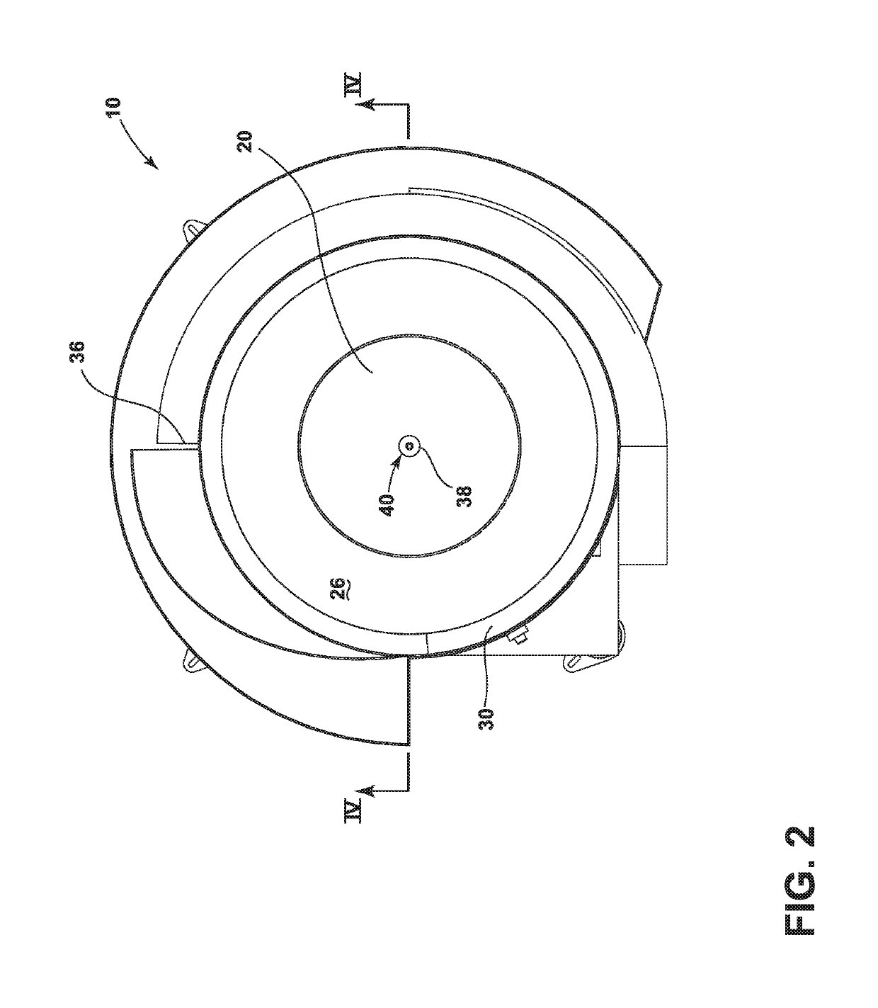
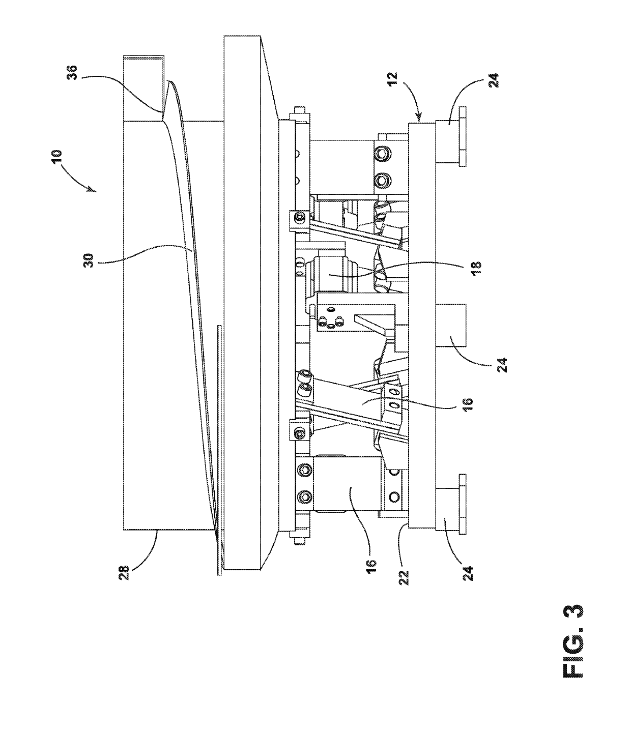
[0010]A vibratory bowl feeder in accordance with one embodiment is illustrated in FIGS. 1-4 and generally designated 10. The vibratory bowl feeder 10 includes a base 12, a bowl 14 above the base 12, a plurality of spring element 16 between the base 12 and the bowl 14, and at least one exciter 18 adapted to impart a vibration on the bowl 10. As also set forth below, the vibratory bowl feeder 10 includes a removable impact cone 20 formed of an impact resistant material. The impact cone 20 deadens the impact from falling industrial workpieces, including for example metal fasteners, and is readily replaceable within minimal labor and tooling to enhance the life expectancy and efficiency of the vibratory bowl feeder 10.

[0011]More specifically, the base 12 includes a rigid frame plate 22 with multiple leg portions 24 that are integrally formed to the rigid frame plate 22. The leg portions 24 include rubber isolators to limit the transfer of vibrations to the surrounding environment. The b...


PUM


Abstract

An improved vibratory bowl feeder is provided. The improved vibratory bowl feeder includes a removable impact cone formed from an impact resistant material to deflect falling industrial workpieces toward the sidewall of a bowl. The impact cone includes a through-hole for a center bolt, the center bolt securing the impact cone to the bowl. An adhesive layer bonds the impact cone to the bowl, which is optionally formed from stainless steel. The impact cone includes a frusto-conical or hemispherical impact surface that deadens the impact from industrial workpieces falling from an overhead hopper. Replacement of the impact cone can be achieved within minimal downtime, and varying impact cones can be selected based on the size and the shape of the industrial workpieces for a given inspection run.

Description

FIELD OF THE INVENTION[0001]The present invention relates to vibratory bowl feeders, in particular vibratory bowl feeders for the handling of bulk fasteners and other industrial workpieces.BACKGROUND OF THE INVENTION[0002]Many automated inspection and sorting machines require the precise orientation and spacing of incoming workpieces. Vibratory bowl feeders are particularly useful for this purpose, and generally include a bowl, a base, and an exciter. The bowl is supported above the base by one or more springs. When activated, the exciter imparts a vibration on the bowl, which vibrates in the vertical direction and in the horizontal direction. Loose workpieces within the bowl propagate upwardly along a spiral track provided on the internal circumference of the bowl for entry, one behind the other, into an inspection and sorting machine.[0003]In many configurations, vibratory bowl feeders are positioned beneath a hopper. During continuous inspection runs, uninspected workpieces from ...

Claims


Application Information

Patent Timeline
Patent Type & Authority Patents(United States)
IPC IPC(8): B65G47/14B65G47/02B65G47/00B65G27/26B65G27/02
CPCB65G27/26B65G27/02B65G47/1421
Inventor STEMMERICH, ROBERTCOSTA, ANTHONY
Owner LINEAR GRP SERVICES LLC
Why Eureka
Eureka Blog
Learn More