Dynamic guest image creation and rollback

a guest image and dynamic technology, applied in the field of data security, can solve the problems of conventional exploit detection schemes producing false negatives, inability to conduct conventional remediation techniques within minutes of infection, and inability to detect exploit schemes that produce false negatives

Active Publication Date: 2019-03-26
FIREEYE SECURITY HLDG US LLC
View PDF561 Cites 129 Cited by
  • Summary
  • Abstract
  • Description
  • Claims
  • Application Information

AI Technical Summary

Problems solved by technology

Over the last decade or so, malicious software has become a pervasive problem for Internet users as most computers include software vulnerabilities that are subject to attack.
Hence, the conventional exploit detection scheme may produce false negatives as many exploits are not captured due to the generalization of the software profiles.
Additionally, once a computer becomes “infected” (e.g., an exploit now resides within internal storage of the computer), conventional remediation techniques are unable to be conducted within minutes of infection.
Rather, such remediation may take hours or even days to occur and may be labor intensive.
It is well known that conventional remediation techniques within an enterprise are arduous and time consuming.
Hence, conventional remediation techniques are slow and may adversely affect productivity of the employee having the infected computer.

Method used


Image

  • Dynamic guest image creation and rollback
  • Dynamic guest image creation and rollback
  • Dynamic guest image creation and rollback

Examples


first embodiment

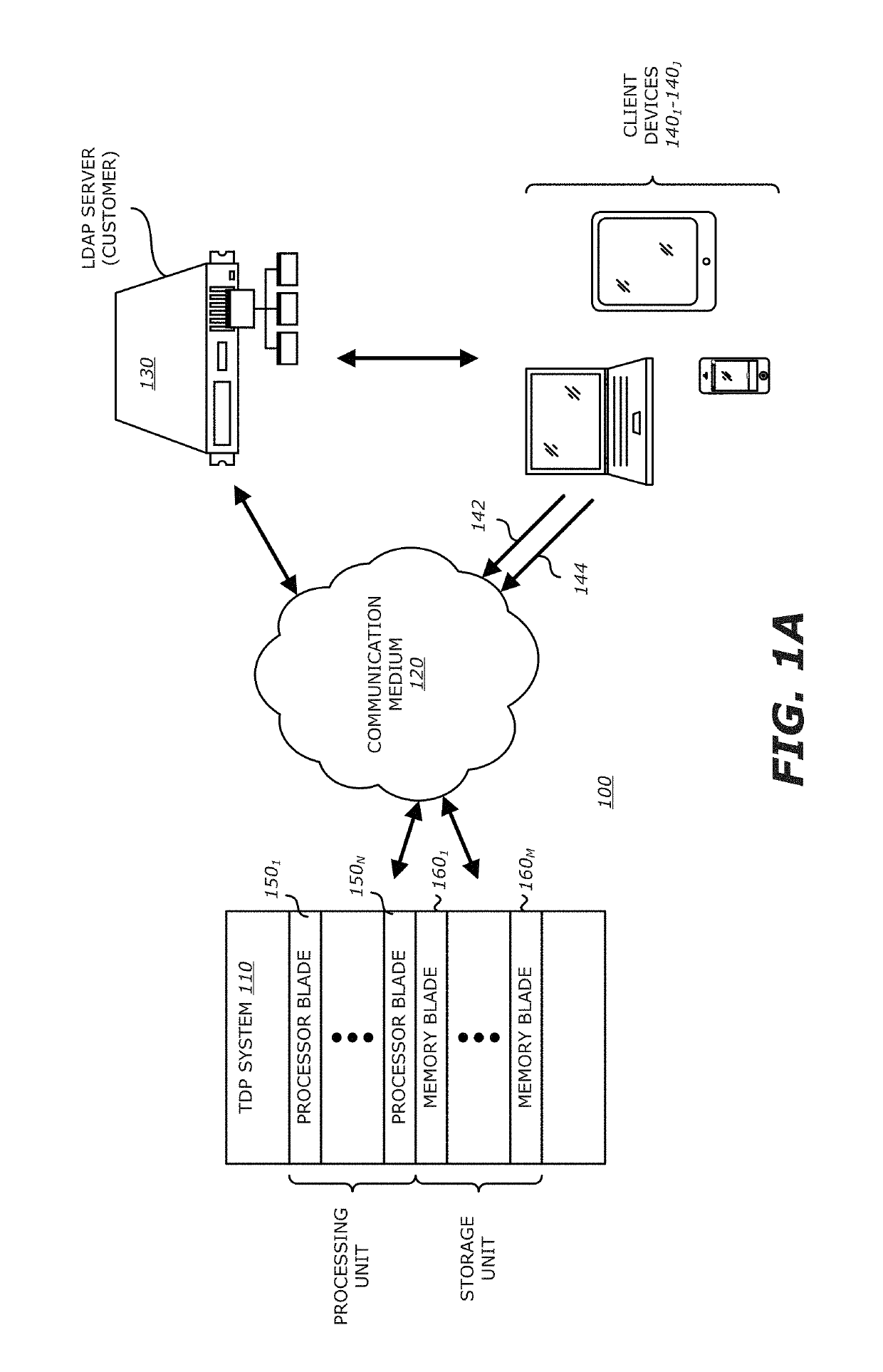
[0042]Referring to FIG. 1A, a block diagram of a client-based exploit detection scheme controlled by a threat detection and prevention (TDP) system utilizing dynamic guest images for VM configuration is shown. Herein, network 100 comprises a TDP system 110 that is configured to monitor network traffic propagating over a communication medium 120 being part of the network 100. The TDP system 110 is communicatively coupled to a Lightweight Directory Access Protocol (LDAP) server 130 and one or more client devices 1401-140J (J≥1).

[0043]As shown in FIG. 1A, TDP system 110 comprises one or more processor blades 1501-150N (N≥1) which may be organized in a vertical, centralized (rack) deployment as shown. The processor blades 1501-150N feature logic that is responsible for performing static and / or dynamic exploit analysis on objects extracted from network traffic propagating over the communication medium 120. For instance, as an illustrative embodiment, each processor blade 150i (1≤i≤N) may...

second embodiment

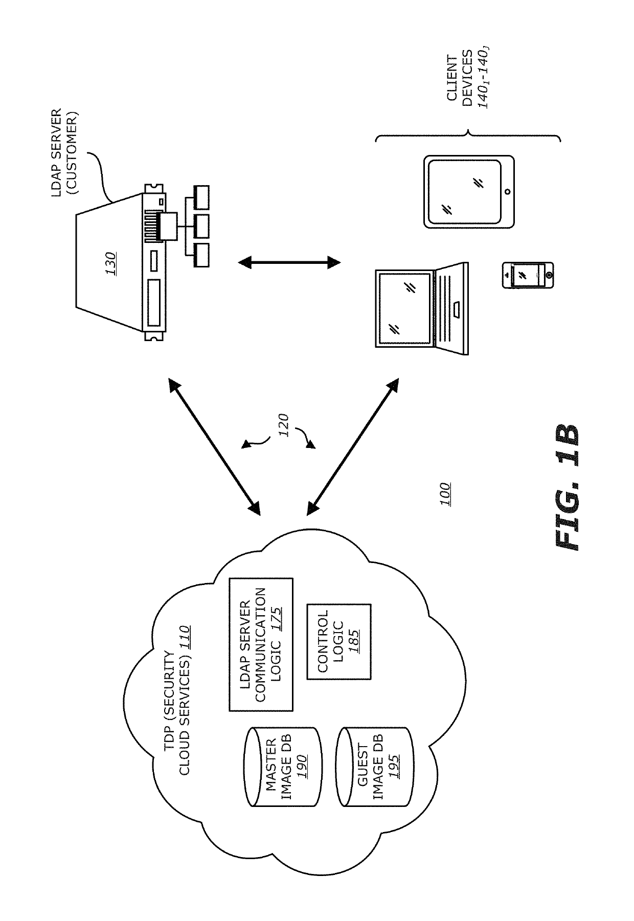
[0051]Referring now to FIG. 1B, a block diagram of a client-based exploit detection scheme controlled by the TDP system utilizing dynamic guest images for VM configuration is shown. Herein, deployed as part of a private network or part of a publicly accessible network, TDP system 110 operates as security cloud services configured to monitor network traffic propagating over the communication medium 120 that partially forms the network 100. Similar to the connectivity described in FIG. 1A, the TDP system 110 is communicatively coupled to LDAP server 130 and one or more client devices 1401-140J.

[0052]As shown in FIG. 1B, the security cloud services forming TDP system 110 comprises one or more databases to maintain master images of an enterprise as well as multiple guest images for each client device 1401-140J and control logic to maintain these databases. At initial set-up, being part of the security cloud services, the LDAP server communication logic 175 may be configured to obtain LD...


PUM


Abstract

According to one embodiment, a computerized method comprises three operations. First, an incoming object is analyzed to determine if the incoming object is suspicious by having characteristics that suggest the object is an exploit. Next, a virtual machine is dynamically configured with a software image representing a current operating state of a targeted client device. The software image represents content and structure of a storage volume for the targeted client device at a time of configuring the virtual machine. Lastly, the object is processed by the virtual machine in order to detect any anomalous behaviors that may cause the object to be classified as an exploit.

Description

1. FIELD[0001]Embodiments of the disclosure relate to the field of data security. More specifically, one embodiment of the disclosure relates to a system, apparatus and method for increasing the accuracy in detecting exploits in flows through the use of dynamic guest images and substantially decreasing the amount of time for remediation of an infected electronic device.2. GENERAL BACKGROUND[0002]Over the last decade or so, malicious software has become a pervasive problem for Internet users as most computers include software vulnerabilities that are subject to attack. For instance, over the past few years, more and more vulnerabilities are being discovered in software that is loaded onto a networked computer or other electronic device. While some vulnerabilities may be addressed through software patches (e.g., to close operating system “OS” vulnerabilities), electronic devices will continue to be targeted by exploits in efforts to acquire sensitive information or adversely affect op...

Claims


Application Information

Patent Timeline
Patent Type & Authority Patents(United States)
IPC IPC(8): G06F21/55
CPCG06F21/552G06F21/566
Inventor GORADIA, HARNISH
Owner FIREEYE SECURITY HLDG US LLC
Why Eureka
Try Eureka