
No miss cache structure for real-time image transformations

a cache structure and real-time image technology, applied in memory addressing/allocation/relocation, instruments, details of portable computers, etc., can solve problems such as user discomfort, potential delay of 16 to 33 milliseconds, and additional latency, so as to minimize dram bandwidth and power, and eliminate the re-fetching of input image data

Active Publication Date: 2019-03-26
MICROSOFT TECH LICENSING LLC
View PDF71 Cites 3 Cited by
  • Summary
  • Abstract
  • Description
  • Claims
  • Application Information

AI Technical Summary

Benefits of technology

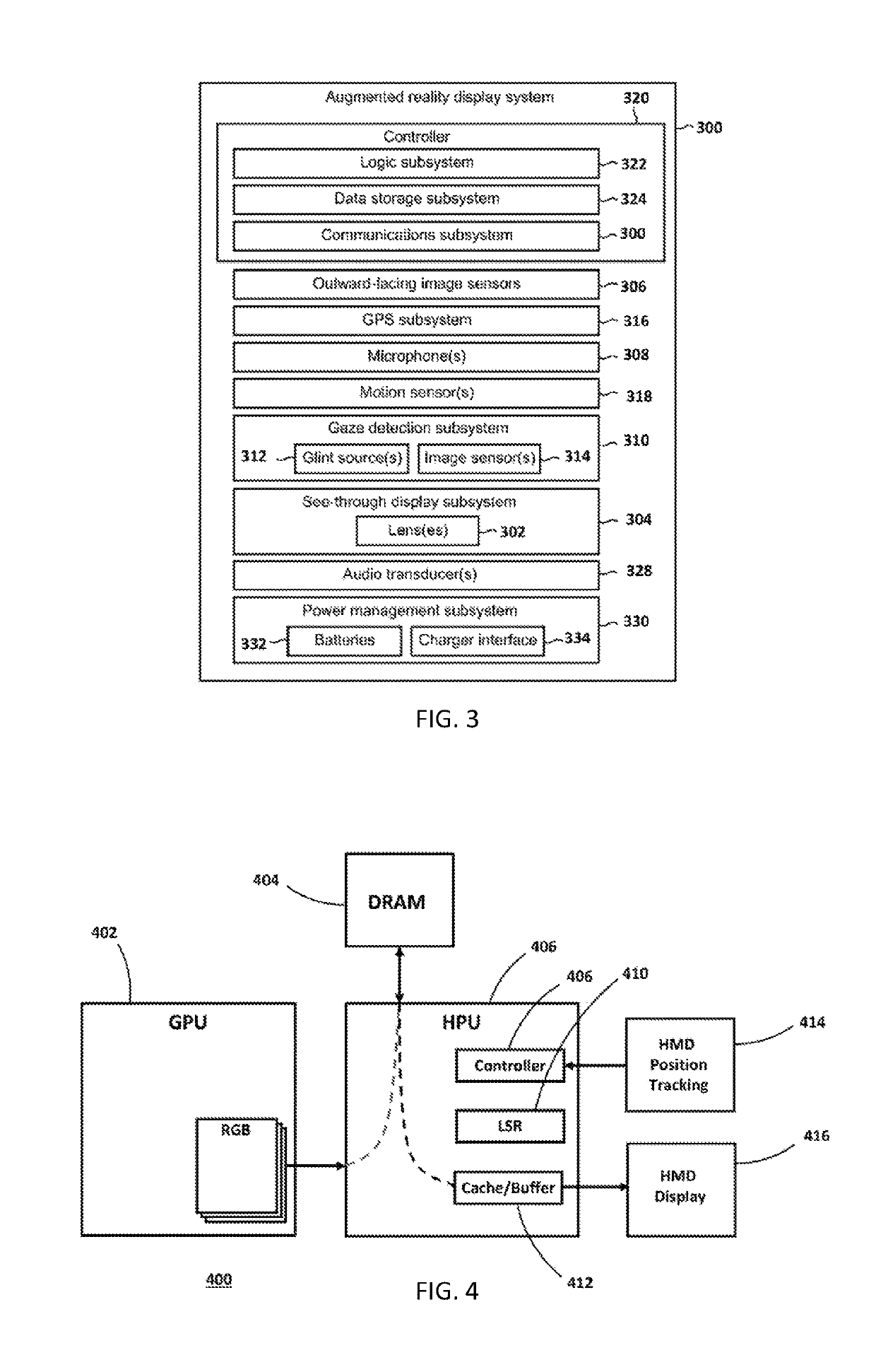
[0006]Systems and methods are disclosed herein for providing improved cache structures and methods that are optimally sized to support a predetermined range of late stage adjustments and in which image data is intelligently read out of DRAM and cached in such a way as to eliminate re-fetching of input image data from DRAM and minimize DRAM bandwidth and power.
[0007]In one embodiment, the cache structure is optimally sized to support a predetermined range of late stage adjustments and is managed such that: the cache / buffer can fetch each line of input image data only once to reduce input bandwidth; the cache can hold multiple lines sufficient to construct the output image (but still much less than the full image); the cache can pre-fetch data before it is needed so that it does not add any additional latency to the image processing pipeline; and the cache can evict input image data only when it is no longer needed to construct the output image, but can automatically evict input image data when it is no longer needed.

Problems solved by technology

However, typical graphics processing units (GPU) currently only render frames between 30 to 60 frames per second, depending on the quality and performance of the GPU.
This results in a potential delay of 16 to 33 milliseconds between the point in time the head position is detected and when the image is actually output to a display.
Additional latency can also be associated with the time it takes to determine the head position and / or delays between the GPU's frame buffer and the final display.
The result is a potentially large error between where the user would expect an image and where the image is displayed, leading to user discomfort.
Since frames can be rendered at a high rate and with high resolution, existing systems employing LSR, can require a large amount of DRAM bandwidth and power.

Method used


Image

  • No miss cache structure for real-time image transformations
  • No miss cache structure for real-time image transformations
  • No miss cache structure for real-time image transformations

Examples


Embodiment Construction

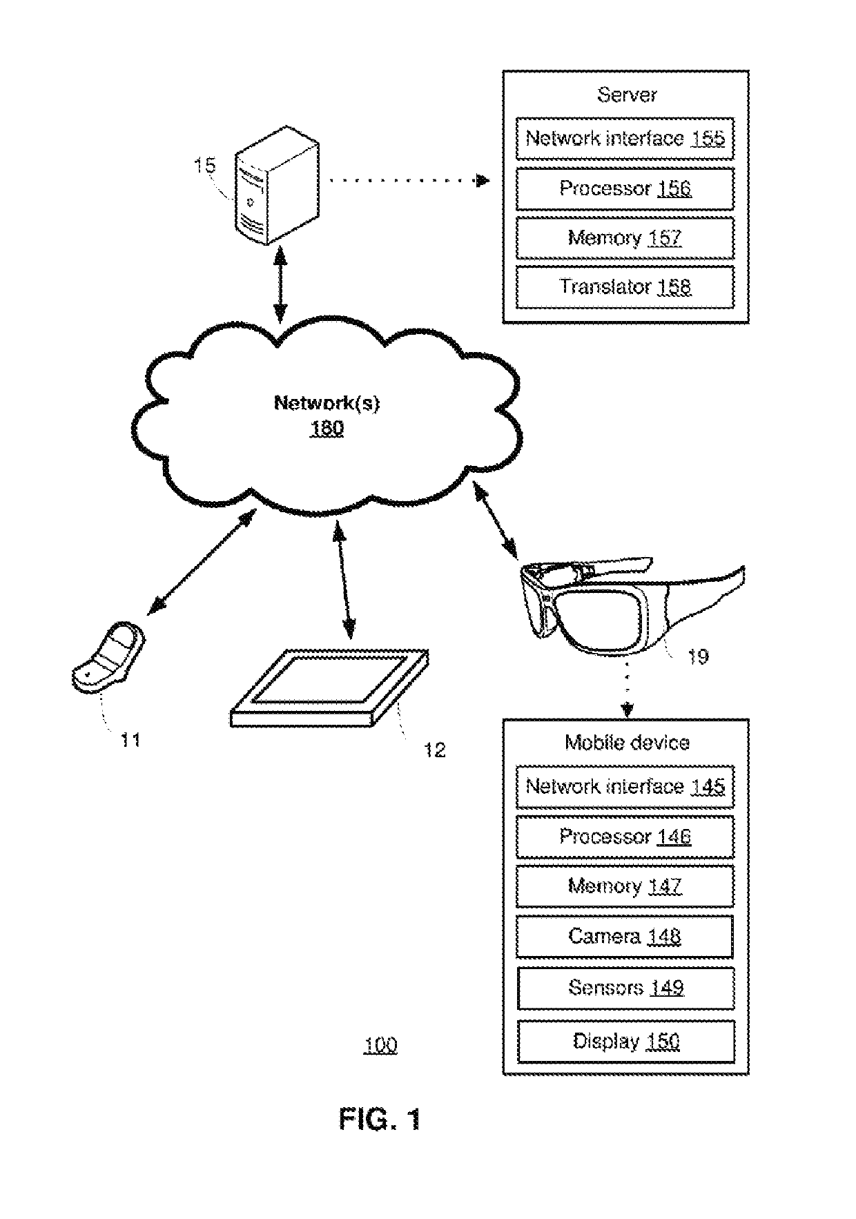
[0020]The following discussion now refers to a number of methods and method acts that may be performed. Although the method acts may be discussed in a certain order or illustrated in a flow chart as occurring in a particular order, no particular ordering is required unless specifically stated, or required because an act is dependent on another act being completed prior to the act being performed.

[0021]As used herein: the terms “input image data” or “GPU image data” may be used interchangeably to refer to image data generated by the GPU of the HMD; and the terms “output image data” or “display image data” may be used interchangeably to refer to data output by the improved cache disclosed herein to render an LSR adjusted display image.

[0022]Subheadings included in the following description are provided for the convenience of the reader, to assist the reader in navigating this disclosure, and are not intended to be limiting or to be used in construing the nature or scope of either this...


PUM


Abstract

Systems and methods are disclosed herein for providing improved cache structures and methods that are optimally sized to support a predetermined range of late stage adjustments and in which image data is intelligently read out of DRAM and cached in such a way as to eliminate re-fetching of input image data from DRAM and minimize DRAM bandwidth and power.

Description

BACKGROUNDBackground and Relevant Art[0001]Mixed reality is a technology that allows virtual imagery to be mixed with a real world physical environment in a display. Systems for mixed reality may include, for example, see through head-mounted display (HMD) devices or smart phones with built in cameras. Such systems typically include processing units which provide the imagery under the control of one or more applications. Full virtual reality environments, in which no real world objects are viewable, can also be supported using HMD and other devices.[0002]Many HMDs also include one or more forward-facing cameras that capture the environment in front of the user as viewed from the user's perspective. Such forward-facing cameras may be depth cameras, which not only capture image data, but also capture depth or surface data about the user's environment. Image data captured from the forward-facing camera may be used by on-board processors located on the HMD to generate mixed reality or v...

Claims


Application Information

Patent Timeline
Patent Type & Authority Patents(United States)
IPC IPC(8): G03H1/00G06T1/20G06T1/60G09G3/00G02B27/01G06F12/02G09G5/395G06F12/0862G06F3/01G06F12/121G06F12/128
CPCG02B27/0103G09G5/395G02B27/017G03H1/0005G06F12/0862G06F12/121G06T1/20G06T1/60G09G3/003G02B2027/014G02B2027/0178G02B2027/0187G03H2001/0088G06F3/011G06F12/0207G06F12/128G06F2212/1016G06F2212/1028G06F2212/1044G06F2212/455G06F2212/6026G09G2360/121G06F1/163G06F3/147G09G2340/0492G09G2350/00Y02D10/00
Inventor OZGUNER, TOLGABRADFORD, JEFFREY POWERSCOMPARAN, MIGUELLEUNG, GENEMUFF, ADAM JAMESHARADEN, RYAN SCOTTJOHNSON, CHRISTOPHER JON
Owner MICROSOFT TECH LICENSING LLC
Learn More