
Storage facility for semiconductor containers

a technology for storage facilities and semiconductors, applied in transportation and packaging, conveyor parts, electric devices, etc., can solve the problems of increasing the complexity and cost of the storage structure structure, and achieve the effect of reducing the amount of air in the holding space that flows out to the exterior space, and reducing the amount of air

Active Publication Date: 2019-03-26
DAIFUKU CO LTD
View PDF12 Cites 1 Cited by
  • Summary
  • Abstract
  • Description
  • Claims
  • Application Information

AI Technical Summary

Benefits of technology

[0008]Thus, a storage facility for semiconductor containers is desired in which the amount of air that flows from the holding space out to the exterior space can be reduced while avoiding increase in complexity and cost of structure of the storage.
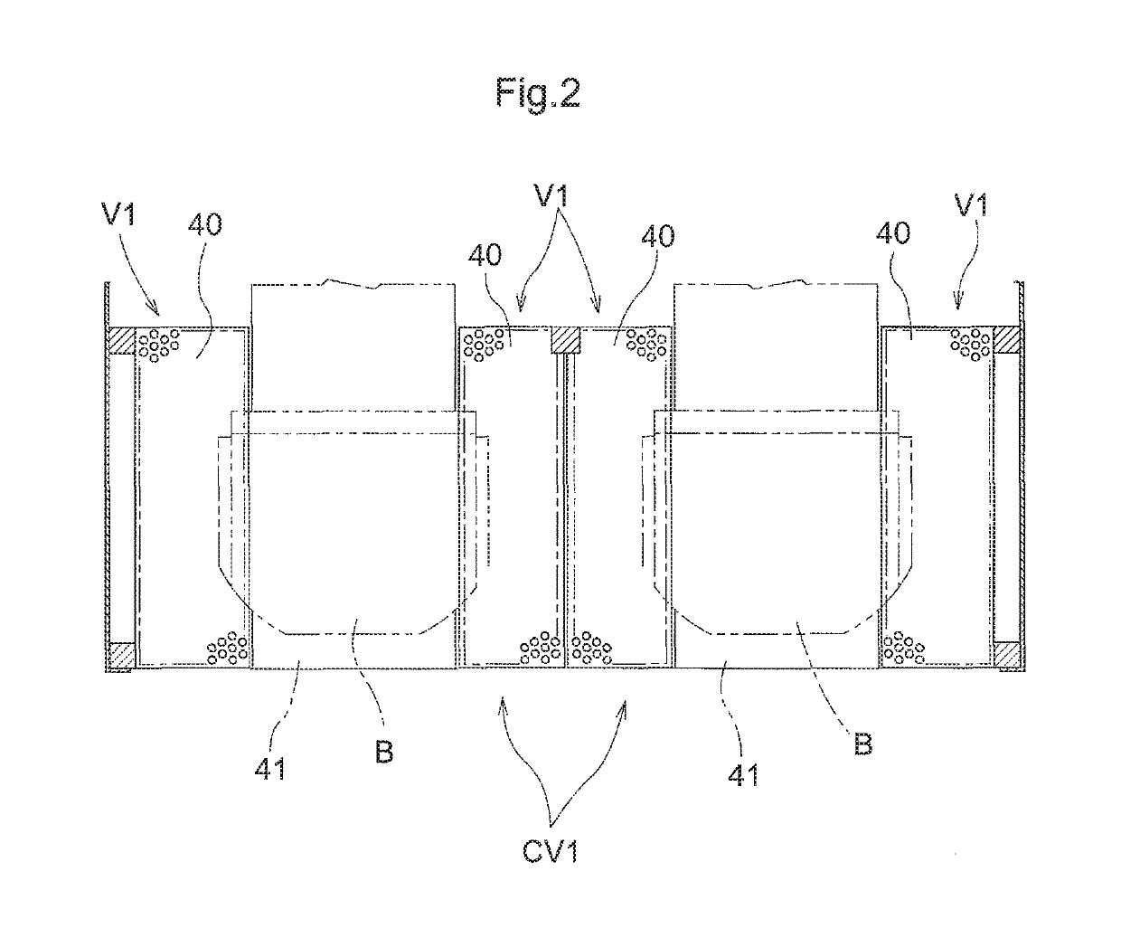
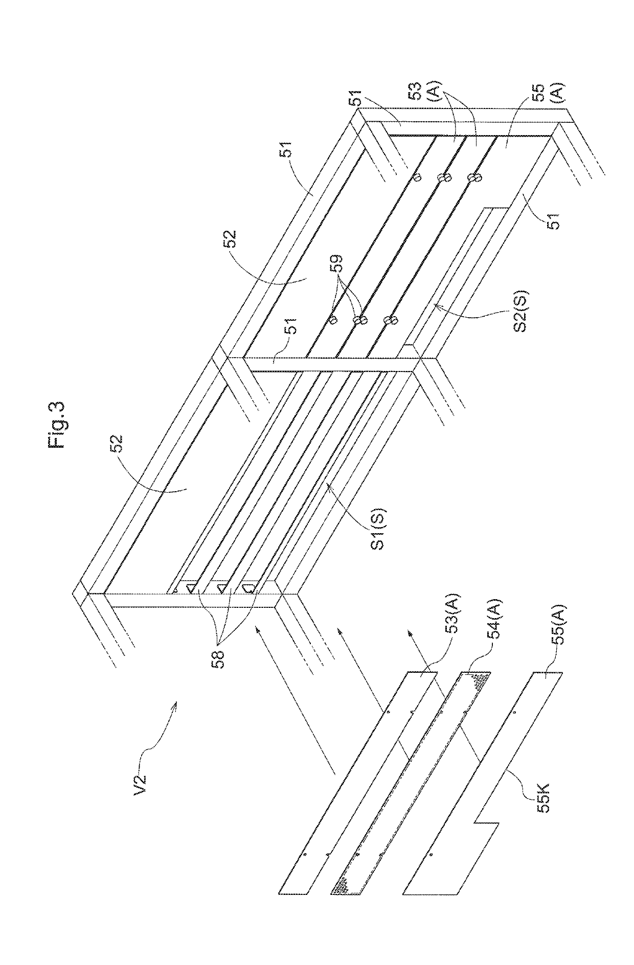
[0010]That is, when air in the holding space (i.e., air containing relatively high concentration inactive gas) is about to flow out or escape to the exterior space through the first opening, air that is about to flow out to the exterior space or air that has once flowed out of the first opening out to the exterior space would be drawn in through the inlet opening located at the position adjacent an edge of the first opening by the drawing-in action of the first drawing-in device. And the air drawn in through the first inlet opening is discharged, or moved, into the discharge space which is outside the holding space and is divided off from the exterior space. This makes it possible to reduce the amount of air around the first opening that flows out to the exterior space.
[0011]Thus, this arrangement makes it possible to reduce the amount of air in the holding space that flows out to the exterior space without having to provide a door to the first opening that can be opened and closed.
[0012]Thus, a storage facility for semiconductor containers can be provided in which the amount of air in the holding space that flows out to the exterior space can be reduced while avoiding increase in complexity and cost of structure of the storage.

Problems solved by technology

In this case, it is necessary to provide, for example, an actuator for opening and closing the door as well as a controller for controlling the opening and closing of the door, which may result in increased complexity and cost of structure of the storage structure.

Method used


Image

  • Storage facility for semiconductor containers
  • Storage facility for semiconductor containers
  • Storage facility for semiconductor containers

Examples


Embodiment Construction

[0019]Embodiments of a storage facility for semiconductor containers are described next with reference to the drawings.

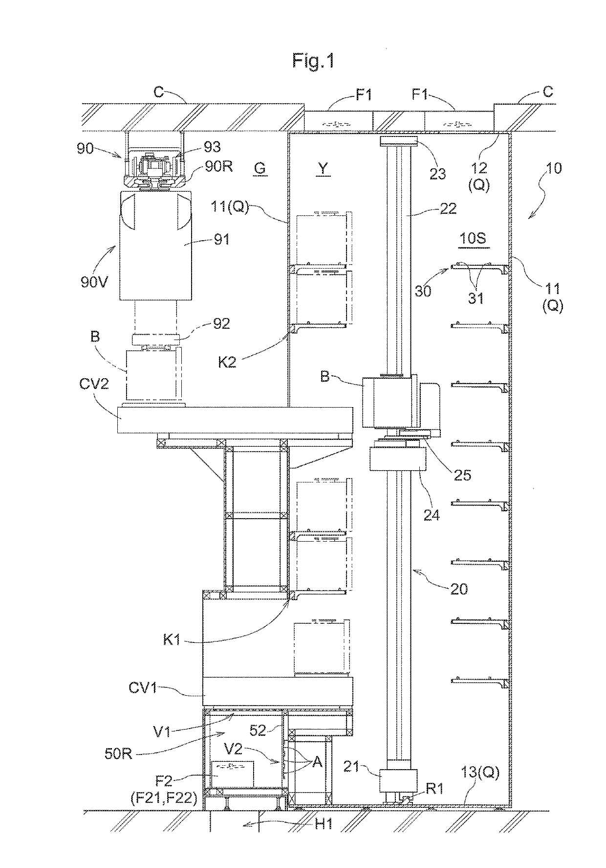
[0020]As shown in FIG. 1, the storage facility for semiconductor containers of the present embodiment includes a storage structure 10 for storing a plurality of containers B (FOUPs) for holding or carrying semiconductor substrates, such that the containers B are arranged one above another in a vertical direction.

[0021]The storage structure 10 includes partitioning walls Q, and holding space Y, and an inactive gas enriching air supply portion. The partitioning walls Q include side wall portions 11 extending along the vertical direction, an upper base portion 12, and a lower base portion 13. The holding space Y is partitioned off from the exterior space G by the partitioning walls Q as seen along the vertical direction. An inactive gas enriching air supply portion supplies inactive gas enriched air, which contains higher concentration of inactive gas (nitrogen etc.) t...


PUM


Abstract

A storage facility for semiconductor containers is provided. The storage structure has partitioning walls including a side wall portion extending along a vertical direction, and holding space partitioned off from exterior space by the partitioning walls. Inactive gas enriched air, which contains higher concentration of inactive gas than concentration of inactive gas contained in air in the exterior space, is supplied to the holding space. A first opening for allowing containers being carried into and out of the storage structure to be moved through the side wall portion is formed in the side wall portion. A first inlet opening is located at a position in the exterior space and adjacent an edge of the first opening. A first drawing-in device is provided to discharge air drawn in through the first inlet opening into discharge space which is outside the holding space and is divided off from the exterior space.

Description

CROSS-REFERENCE TO RELATED APPLICATION[0001]This application claims priority to Japanese Patent Application No. 2015-065737 filed Mar. 26, 2016, the disclosure of which is hereby incorporated in its entirety by reference.FIELD OF THE INVENTION[0002]The present invention relates to a storage facility for semiconductor containers comprising a storage structure for storing containers for holding one or more semiconductor substrates, wherein the storage structure has partitioning walls including a side wall portion extending along a vertical direction, and holding space partitioned off from exterior space by the partitioning walls, wherein inactive gas enriched air, which contains higher concentration of inactive gas than concentration of inactive gas contained in air in the exterior space, is supplied to the holding space, wherein a first opening for allowing containers being carried into and out of the storage structure to be moved through the side wall portion is formed in the side w...

Claims


Application Information

Patent Timeline
Patent Type & Authority Patents(United States)
IPC IPC(8): H01L21/677H01L21/67
CPCH01L21/67769H01L21/67736H01L21/67017
Inventor MICHISHITA, DAIKIYAMAKAWA, MIHO
Owner DAIFUKU CO LTD
Learn More