Exposure apparatus and device manufacturing method

a technology of exposure apparatus and manufacturing method, which is applied in the direction of photomechanical treatment, printing, instruments, etc., can solve the problems of unfavorable supply of holding units, difficult calibration of calibration illuminance sensors in the main region, and inability to accurately calibrate the sensitivity of measurement devices, etc., to suppress the increase in cost and complexity of the arrangement of exposure apparatuses. , the effect of high accuracy

Active Publication Date: 2009-12-17
CANON KK
View PDF9 Cites 2 Cited by
  • Summary
  • Abstract
  • Description
  • Claims
  • Application Information

AI Technical Summary

Benefits of technology

[0014]The present invention provides a technique for detecting the position of an illuminance sensor with high accuracy while suppressing increases in the cost and the complexity of the arrangement of an exposure apparatus.

Problems solved by technology

This makes it impossible to correctly calibrate the sensitivity of the measurement device.
Thus, it is becoming increasingly difficult to set the calibration illuminance sensor in the main region.
Unfortunately, when an improvement in the throughput is of prime importance, it is unfavorable to provide a holding unit, for holding the calibration illuminance sensor in sensitivity calibration, to the substrate stage.
This is because such a holding unit complicates the substrate stage, leading to an increase in its weight.
The problem in this scheme is that an error upon attaching the arm to the driving mechanism or attaching the illuminance sensor on the arm degrades the positioning accuracy of the illuminance sensor.
Furthermore, the attachment error directly turns into a positioning error because a driving mechanism as described above generally does not cooperate with a position sensor indispensable to precisely position the illuminance sensor as the positioning target object.
Also, additionally providing a high-accuracy position sensor to the exposure apparatus increases the complexity of the exposure apparatus and the manufacturing cost.

Method used


Image

  • Exposure apparatus and device manufacturing method
  • Exposure apparatus and device manufacturing method
  • Exposure apparatus and device manufacturing method

Examples


first embodiment

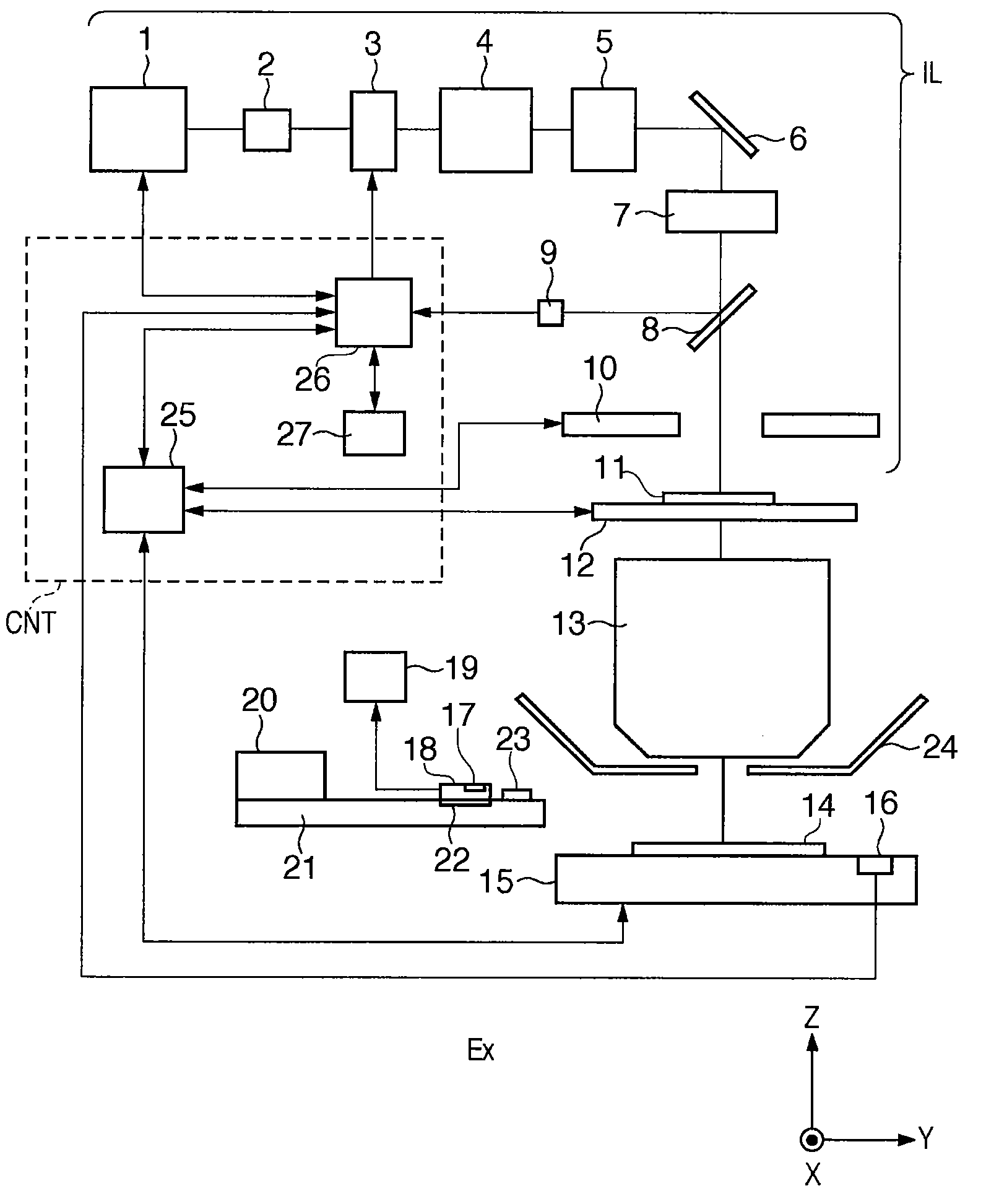
[0025]FIG. 1 is a view showing the schematic arrangement of an exposure apparatus of the step & scan scheme according to a preferred embodiment of the present invention. The step & scan scheme means a scheme of projecting the pattern of an original 11 onto a substrate (e.g., a wafer) 14 by a projection optical system 13 while synchronously scanning them, thereby exposing the substrate 14. Note that the original 11 is scanned so that its pattern region passes through the illumination region illuminated by an illumination system IL. The illumination region is defined by a masking blade 10 serving as a light-shielding member. Note that the present invention is also applicable to an exposure apparatus of the step & repeat scheme.

[0026]FIG. 1 adopts an X-Y-Z coordinate system in which a direction parallel to the scanning direction of a substrate stage 15 and original stage 12 is defined as the Y direction, and a direction perpendicular to the Y direction is defined as the X direction.

[00...

second embodiment

[0057]The second embodiment of the present invention will be explained below. Note that details which are not particularly referred to in the second embodiment can be the same as in the first embodiment. In the second embodiment, a measurement device 16 is calibrated based on the position detection result obtained by an illuminance sensor 18, and the illuminance distribution on the image plane of a projection optical system 13 measured using the measurement device 16 while a masking blade 10 is set at the substrate exposure position.

[0058]More specifically, first, a controller CNT detects the position of the illuminance sensor 18 in accordance with the first embodiment. Next, the controller CNT acquires a first measurement value by causing the illuminance sensor 18 to measure the illuminance while the position of the illuminance sensor 18 remains the same as during the position detection of the illuminance sensor 18 and the masking blade 10 is set at the substrate exposure position....


PUM


Abstract

An exposure apparatus is configured to project a pattern of an original illuminated by an illumination system onto a substrate by a projection optical system to expose the substrate, and comprises a light-shielding member configured to define a position at which light falls on an image plane of the projection optical system, an illuminance sensor configured to measure an illuminance on the image plane, and a controller configured to detect a position, on the image plane, of the illuminance sensor, wherein the controller is configured to detect the position of the illuminance sensor based on the output from the illuminance sensor obtained while moving the light-shielding member so that a position at which light falls on the image plane moves along the image plane.

Description

BACKGROUND OF THE INVENTION[0001]1. Field of the Invention[0002]The present invention relates to an exposure apparatus and a method of manufacturing a device using the same.[0003]2. Description of the Related Art[0004]An exposure apparatus projects the pattern of an original (also called a reticle or mask) onto a substrate by a projection optical system to expose the substrate, using an excimer laser or a mercury lamp as an exposure light source. The substrate is coated with a photoresist, on which a latent image is formed by exposure.[0005]The exposure process of exposing a substrate by the exposure apparatus requires precise exposure dose control on the substrate. A measurement device for measuring the illuminance of the exposure light which falls on the image plane (the plane on which a substrate is positioned) of the projection optical system is mounted on the substrate stage of the exposure apparatus.[0006]Since the sensitivity of the measurement device is not constant under al...

Claims


Application Information

Patent Timeline
Patent Type & Authority Applications(United States)
IPC IPC(8): G03B27/42
CPCG03B27/42G03F7/7085G03F7/70558
Inventor TAI, MASAKI
Owner CANON KK
Why Eureka
Try Eureka