Geared hydraulic apparatus

a hydraulic apparatus and geared technology, applied in the direction of rotary piston engines, portable lifting, rotary or oscillating piston engines, etc., can solve the problems of direct operating noise, uncontrollable local stress peak, and induced noise that can reach unpredictable levels, so as to minimise the pulsation of fluid and minimise the noise. , the effect of ripple nois

Active Publication Date: 2013-10-15
SETTIMA FLOW MECHANISMS SRL +1
View PDF19 Cites 3 Cited by
  • Summary
  • Abstract
  • Description
  • Claims
  • Application Information

AI Technical Summary

Benefits of technology

[0014]In a particular embodiment, the gearwheels are helical. In this case, it is possible to adopt even a significant helix angle without there being a risk of by-pass between inlet and outlet, i.e. in particular between intake and delivery in the case of positive displacement pumps. The helical toothing makes it possible to minimise the noise due to meshing, which is instead characteristic of straight-cut toothing because of the non-gradual passage of the contact from one pair of teeth to the next between the co-operating teeth of the gearwheels. The helical toothing further makes it possible to minimise the delivery pulsation of the fluid, and therefore the ripple noise. The overlap of the helical toothing may preferably be equal or close to unity.
[0015]The hydraulic apparatus of the present invention may have undercuts or pockets or ducts provided on the faces of the lateral abutment means or supports or bushes of the gearwheels, arranged in communication with the closed fluid entrapment areas which form in the aforesaid meshing configurations at the end cross-sections of the gearwheels, in order to discharge the trapped fluid towards the appropriate high or low pressure side, port or gate. The dimensioning of said discharge pockets is simple and optimum, since the by-pass between the inlet side and the outlet side is prevented by the toothing itself, in the meshing configuration in which the closed fluid entrapment area is substantially reduced to zero and there is a substantial absence of clearance between the tooth head of one gearwheel and the tooth bottom of the other gearwheel.

Problems solved by technology

A particular drawback arising in the aforesaid geared pumps of conventional type, generally with involute tooth profile, is the fact that the pumped fluid is encapsulated, i.e. trapped, and compressed or in any case subjected to volume variations in the spaces enclosed between the profiles of the teeth in the meshing zone, thus giving rise to harmful and uncontrolled peaks of local stress which are the cause of direct operating noise. FIG. 1, purely by way of example, shows diagrammatically in cross-section the meshing zone of the two gearwheels 1 and 2 of a conventional type of geared hydraulic apparatus, in a specific angular position, in which the configuration of the respective meshing teeth 3 and 4 entails the generation of closed areas 5 and 6 in which the fluid is trapped.
Besides the direct operating noise indicated above, there is also a known problem arising from the phenomenon of irregularity, or “ripple”, in the transfer of the fluid which entails an indirect operating noise, known as ripple noise, linked to the flow rate pulsation and therefore pressure pulsation in the user circuit.
The induced noise may also reach unpredictable levels in the case where the aforesaid members resonate with the oscillation or ripple frequency.

Method used


Image

  • Geared hydraulic apparatus
  • Geared hydraulic apparatus
  • Geared hydraulic apparatus

Examples


Embodiment Construction

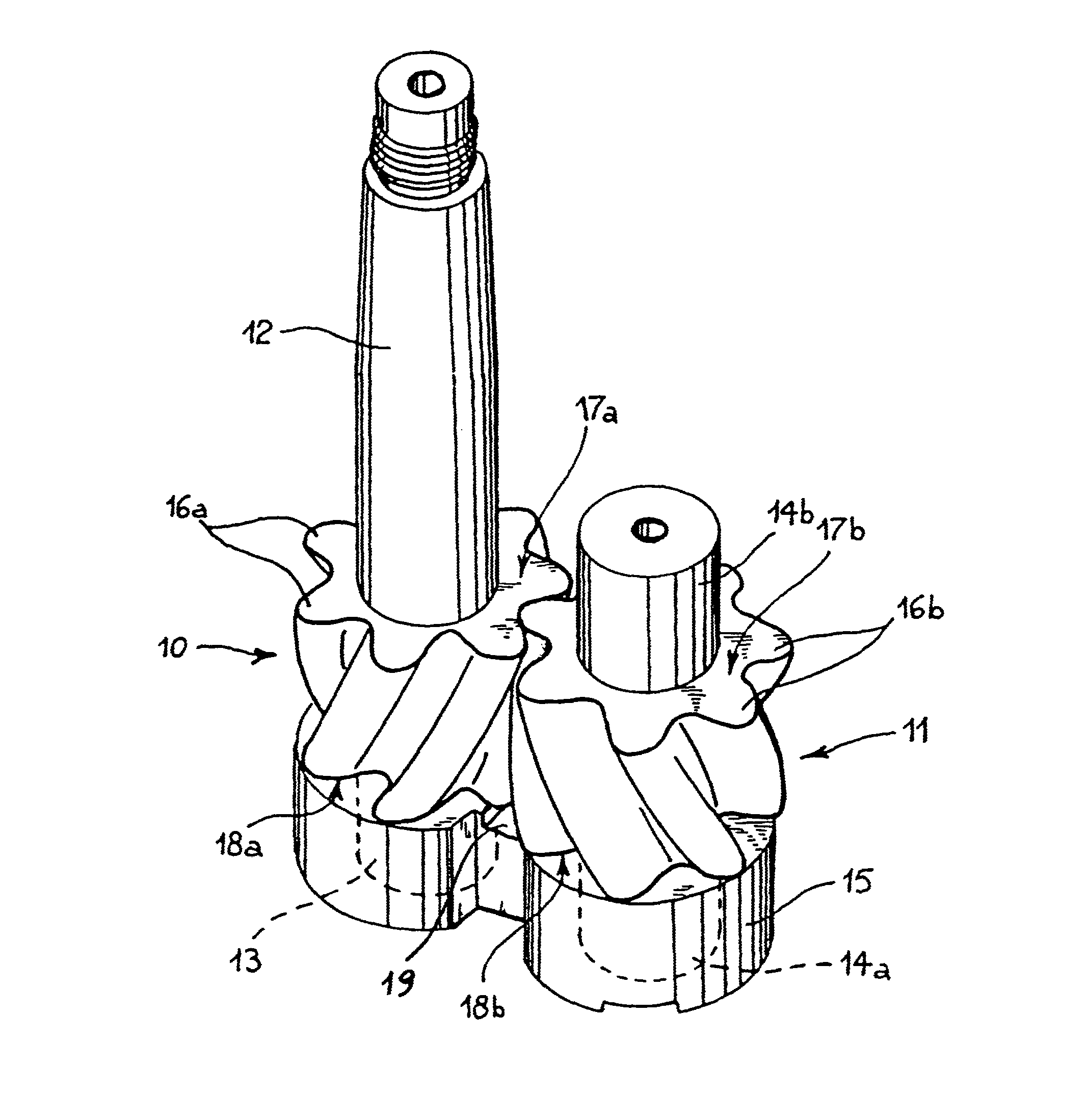
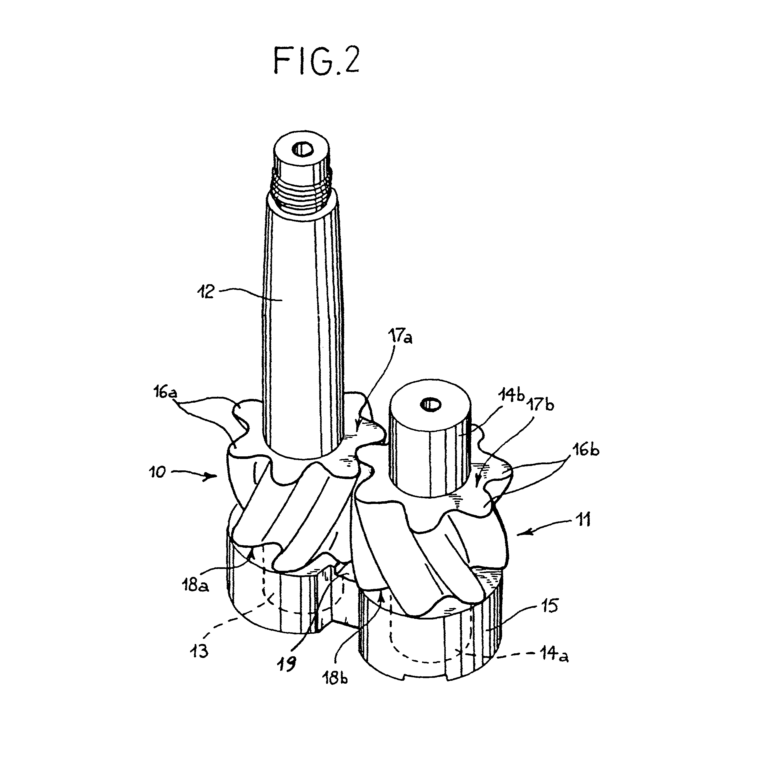
[0027]Although the following discussion is provided with reference to a pump, identical reasoning and considerations may be applied to similar hydraulic motors.

[0028]With reference to FIG. 2, a rotary positive displacement pump of the type with transverse flow comprises a first and a second gearwheel or rotor 10, 11. The first gearwheel 10 is connected, integrally or by means of a type of fixing generally known in the field, to a drive shaft 12 which, when the pump is in use, receives the motion from a drive member (not shown). The second gearwheel 11 meshes with the first gearwheel and, in use, is driven in rotation by this latter. Both the gearwheels 10, 11 are provided with stubs or shafts 13, 14a, 14b mounted to be rotatable, like the drive shaft 12, in a sealed manner on abutments or bushes 15, only one of which is shown in FIG. 2 for clarity of illustration. The gearwheels 10, 11 are enclosed, as is well known in the field of rotary pumps, in a casing (not shown) provided with...


PUM


Abstract

An improved geared hydraulic apparatus, comprising a pair of meshing gearwheels, mounted to be reciprocally rotatable in a casing between an inlet side and an outlet side for a fluid having, in use, a substantially transverse flow with respect to the axes of rotation of the gearwheels. The meshing gearwheels create, during their reciprocal rotation, progressive meshing configurations between respective co-operating teeth. In at least one of said progressive meshing configurations is defined, in at least one cross-section of the gearwheels, at least one closed area between respective fluid entrapment teeth. The closed area decreases until it is substantially cancelled out at and around at least one other, separate progressive meshing configuration between the aforesaid respective co-operating teeth.

Description

BACKGROUND OF THE INVENTION[0001]The present invention relates to an improved geared hydraulic apparatus. The invention has been developed with particular reference to geared rotary positive displacement pumps, to which special reference will be made in the continuation of the present description, but the principles of the invention may also be applied in exactly the same way to geared hydraulic motors, which are therefore understood to be included within the scope of the present invention.SUMMARY OF THE INVENTION[0002]Geared rotary positive displacement pumps are generally constituted by two gearwheels, in the majority of cases of the spur gear type, one of which, known as the drive gear, is connected to a drive shaft and drives in rotation the other gearwheel, known as the driven gear. A particular drawback arising in the aforesaid geared pumps of conventional type, generally with involute tooth profile, is the fact that the pumped fluid is encapsulated, i.e. trapped, and compress...

Claims


Application Information

Patent Timeline
Patent Type & Authority Patents(United States)
IPC IPC(8): F01C21/00F04C2/00F03C4/00F04C18/00F03C2/00
CPCF01C1/084F01C1/088F04C2/088F04C2/084Y10T74/19972
Inventor MORSELLI, MARIO ANTONIO
Owner SETTIMA FLOW MECHANISMS SRL
Why Eureka
Try Eureka