Torque rod and manufacturing method thereof

a technology of torque rods and manufacturing methods, applied in the field of torque rods, can solve the problems of poor versatility and poor method, and achieve the effects of reducing costs, reducing costs, and facilitating determination or fixation

Active Publication Date: 2019-04-02
YAMASHITA RUBBER CO LTD
View PDF7 Cites 0 Cited by
  • Summary
  • Abstract
  • Description
  • Claims
  • Application Information

AI Technical Summary

Benefits of technology

[0040]According to the first feature of the present invention, by selecting such combination between the small ring torsion spring and the large ring spring ratio that transmission characteristics in the transmission characteristic map in the specific rod length and large ring spring are less than 100 N / mm, it is possible to realize the torque rod which is durable and has such flat characteristics that the peak value of the transmission characteristics is less than 100 N / mm. In addition, the small ring torsion spring and the large ring spring ratio which are used as the parameters can be easily determined or fixed.
[0041]According to the second feature of the present invention, since the inner member (32) of the large ring section (30) is made of pipe, there is no need to use the inner member of special deformed shape. Therefore, cost reduction can be achieved while obtaining the torque rod which is durable and has the flat characteristics.
[0042]According to the third feature of the present invention, since the cheap round pipe member is used for the inner member (32) of the large ring section (30), the costs can be further lowered.
[0043]According to the fourth feature of the present invention, the large ring elastic center distance is set up falling within the predetermined pipe zone, whereby the use of the inner member made of pipe (containing the round pipe) has become possible.
[0044]According to the fifth feature of the present invention, in the graph representing the large ring elastic center distance (A) on the vertical axis and the large ring spring ratio (R) on the horizontal axis, the zone bounded by the large ring spring ratios of R=0.2˜1.0, the straight line of A=−23R+21 and the straight lines extending in parallel with the straight line A=−23R+21 can be set up as the pipe zone.
[0045]According to the sixth feature of the present invention, since each of the outer members (21) and (31) of the small ring section (20) and the large ring section (30) is made of resin and formed integral with the rod section (40), the manufacturing can be facilitated in comparison with the case where these components are formed separately. In addition, the degree of freedom relative to the shape of the outer member (31) of the large ring section (30) can be increased.

Problems solved by technology

Thus, this method is poor in versatility.
Thus, this method is also poor in versatility.

Method used


Image

  • Torque rod and manufacturing method thereof
  • Torque rod and manufacturing method thereof
  • Torque rod and manufacturing method thereof

Examples


Embodiment Construction

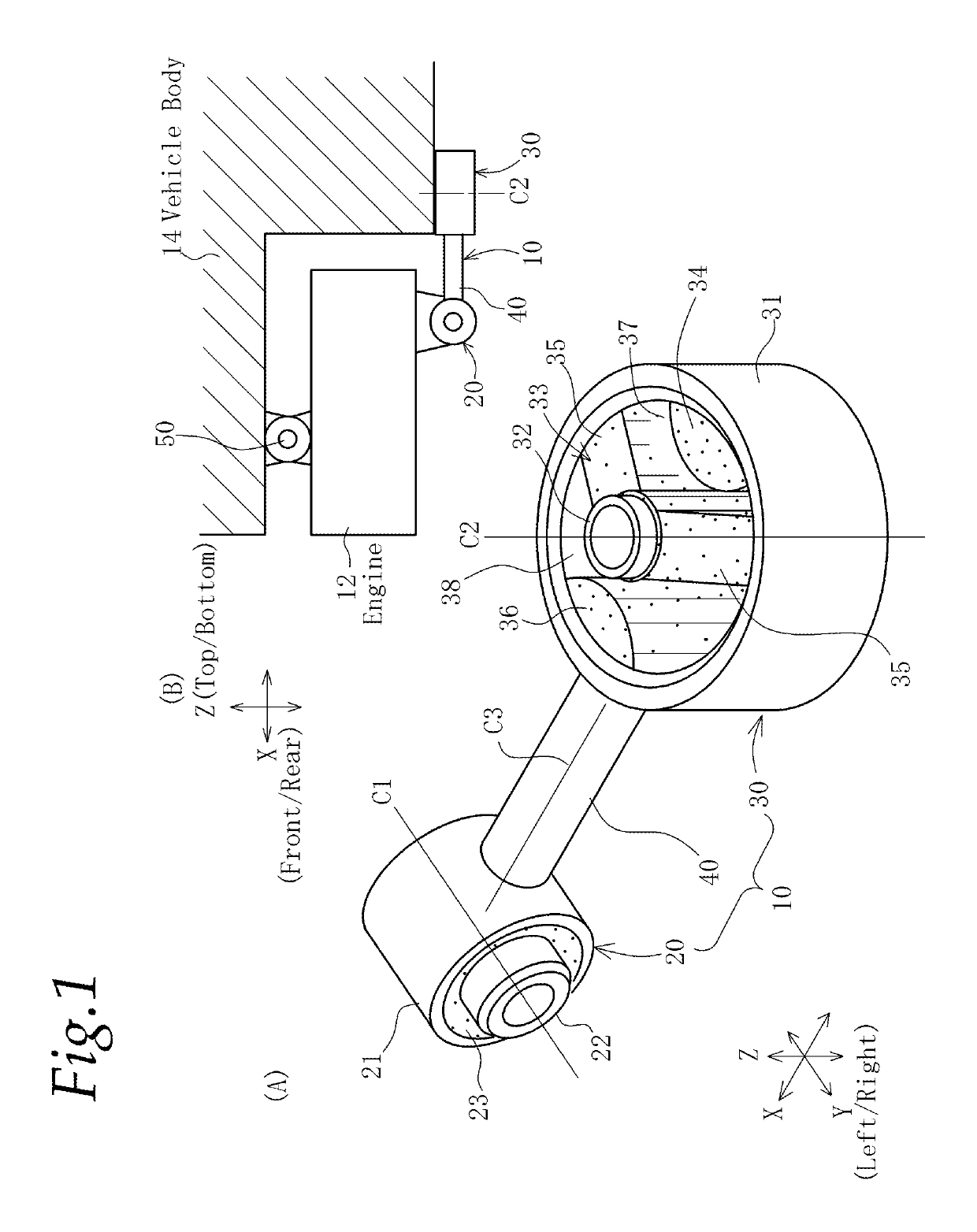
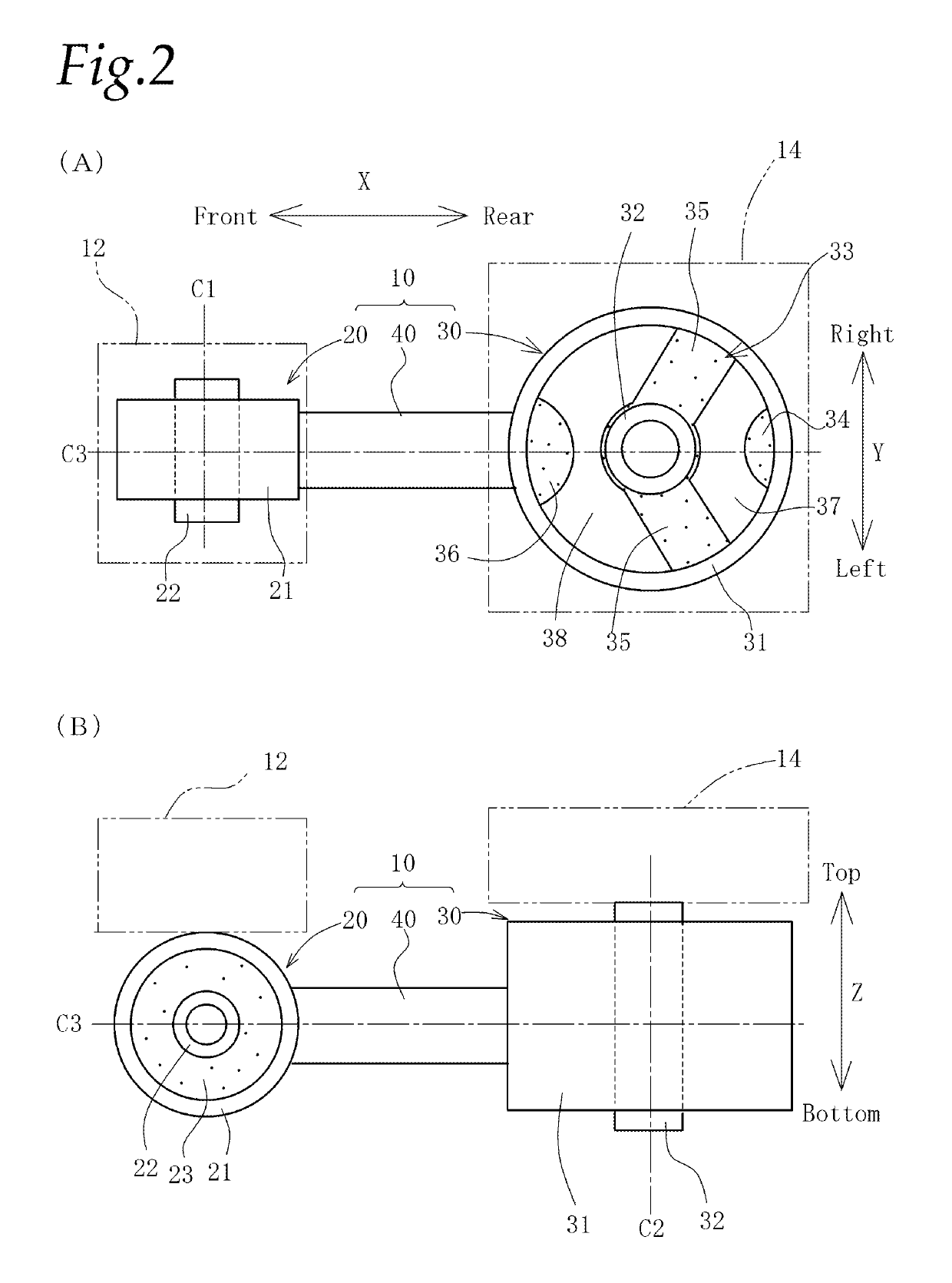
[0058]Referring to FIGS. 1 and 2, an outline of a torque rod 10 according to the present invention will be explained first. However, a structure in external appearance is the same as those explained in the above background art, and there are differences only in values of transmission characteristics and parameters such as a large ring spring ratio, a large ring elastic center distance and the like. Therefore, the explanation with respect to like or corresponding parts in the structure in external appearance will be omitted, and so details and features will be explained hereunder.

[0059]Outer members 21, 31 and a rod section 40 are made of proper light materials such as synthetic resin and the like which have a lower specific gravity than aluminum and formed integral with each other. This torque rod is manufactured by a publicly known method such that a preliminary molding integrally formed with a small ring inner member 22, a small ring elastic member 23 and a large ring inner member...


PUM


Abstract

A torque rod includes a small ring section to be connected to an engine, a large ring section to be connected to a vehicle body, and a rod section providing a connection between the small ring section and the large ring section. The large ring section includes an outer member connected to the rod section, an inner member to be connected to the vehicle body, and a large ring elastic member providing a connection between the outer member and the inner member. Based on a transmission characteristic map, which is prepared by mapping transmission characteristics of the torque rod that are determined by a rod length, a small ring torsion spring, a large ring spring and a large ring spring ratio as parameters, such a combination of parameters that the transmission characteristics are less than 100 N / mm is selected.

Description

TECHNICAL FIELD[0001]The present invention relates to a torque rod for providing a connection between an engine and a vehicle body in a vibration isolating manner and a manufacturing method thereof.BACKGROUND ART[0002]FIGS. 1 and 2 show a torque rod in accordance with the present invention, and a whole structure is schematically illustrated as a structure of a general torque rod. FIG. 1(A) is a perspective view of the torque rod. FIG. 1(B) is a schematic view showing a state of an engine being supported in a vibration isolating manner. FIG. 2(A) is a plan view of the torque rod, and FIG. 2(B) is a front view thereof.[0003]In the following description of the present invention, each orientation such as front, rear, left, right, upper side and lower side shall be determined based on each direction of the vehicle onto which the engine is loaded. In particular, with respect to forward and rearward directions of a large ring section, the side of a small ring section shall be a forward dir...

Claims


Application Information

Patent Timeline
Patent Type & Authority Patents(United States)
IPC IPC(8): F16F15/02F16F1/38B60K5/12F16F15/08
CPCB60K5/1208B60K5/1216B60K5/1241F16F15/085F16F1/3849F16F2238/024F16F2236/12
Inventor SATOU, YOUSUKE
Owner YAMASHITA RUBBER CO LTD
Why Eureka
Try Eureka