
Electronic device having antenna structure

a technology of electronic devices and antennas, applied in the direction of slot antennas, antenna details, antennas, etc., can solve the problems of reducing the ability of the antenna affecting the communication quality of the mobile communication device, and easy to affect the antenna's radio characteristics, etc., to achieve good ability to send and receive signals

Active Publication Date: 2019-04-02
WISTRON NEWEB
View PDF36 Cites 0 Cited by
  • Summary
  • Abstract
  • Description
  • Claims
  • Application Information

AI Technical Summary

Benefits of technology

This configuration allows mobile communication devices to maintain both a metallic appearance and robust signal sending and receiving capabilities, unaffected by the metal back cover's design requirements.

Problems solved by technology

However, radiation characteristics of the antenna are easily affected by surrounding metal objects.
For example, the back cover causes a shielding effect for the antenna and decreases the ability of the antenna to send and receive signals.
Therefore, when a back cover is disposed due to design requirements for appearance in a mobile communication device, the communication quality of the mobile communication device is often affected as well.
In other words, the appearance design of metallic texture infuses a sense of fashion for the mobile communication device, but also brings even larger challenge for the design of antenna in the mobile communication device.

Method used


Image

  • Electronic device having antenna structure
  • Electronic device having antenna structure
  • Electronic device having antenna structure

Examples


Embodiment Construction

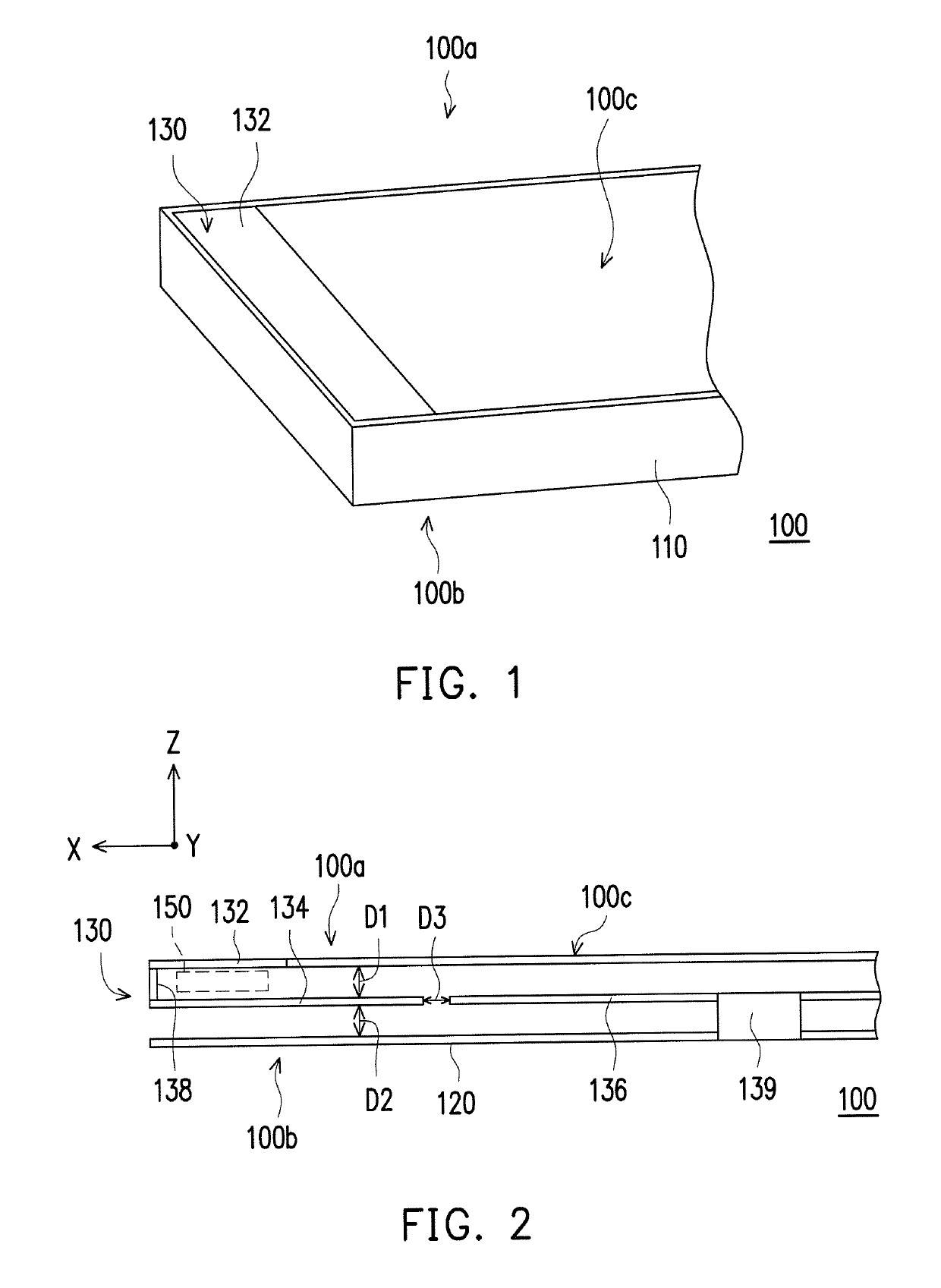
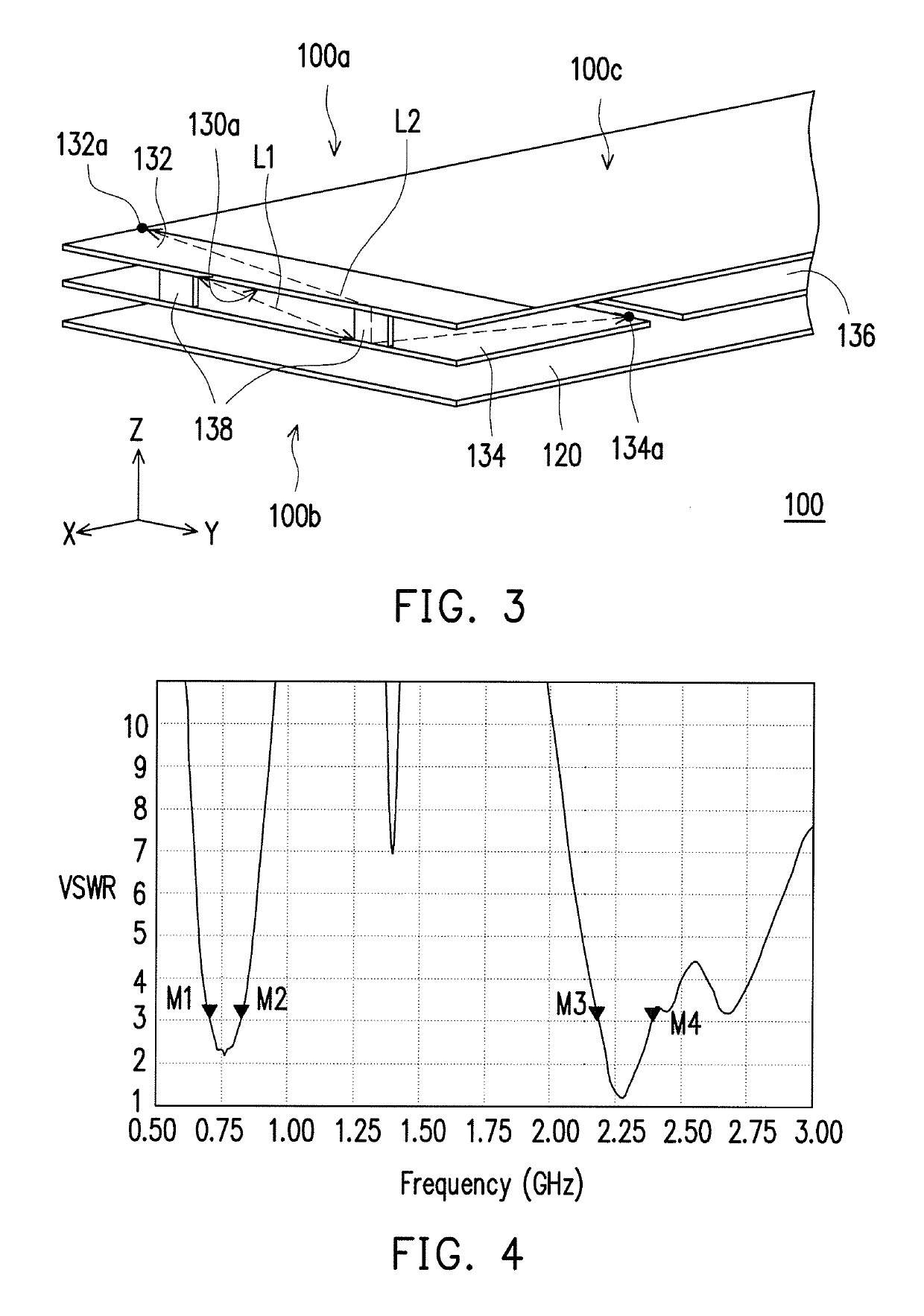
[0017]FIG. 1 is a partial perspective view of an electronic device according to one embodiment of the invention. FIG. 2 is a perspective view illustrating a partial structure of the electronic device in FIG. 1. FIG. 3 is a side view of the electronic device in FIG. 2. Referring to FIGS. 1-3, the electronic device 100 of the embodiment is, for example, a smart phone or other kinds of hand-held electronic devices. The electronic device 100 of the embodiment has a front side 100a, a rear side 100b and a display surface 100c. The front side 100a is opposite to the rear side 100b, and the display surface 100c is positioned at the front side 100a. The electronic device 100 includes an outer frame 110 and a back cover 120. The outer frame 110 is disposed at the peripheral edge of the electronic device 100. The back cover 120 is disposed at the rear side 100b of the electronic device 100, and the back cover 120 and the outer frame 110 shield internal components of the electronic device 100 ...


PUM


Abstract

An electronic device has a front side and a rear side opposite to each other and includes a back cover and an antenna structure. The back cover is disposed at the rear side. The antenna structure includes a first radiation portion, a second radiation portion and a ground portion. The first radiation portion is disposed at the front side. The second radiation portion is disposed between the first radiation portion and the back cover and is connected to the first radiation portion. The ground portion is disposed between the first radiation portion and the back cover, wherein the second radiation portion is grounded to the back cover through the ground portion.

Description

CROSS-REFERENCE TO RELATED APPLICATION[0001]This application claims the priority benefit of Taiwan application serial no. 104101775, filed on Jan. 20, 2015. The entirety of the above-mentioned patent application is hereby incorporated by reference herein and made a part of this specification.BACKGROUND OF THE INVENTION[0002][Field of the Invention][0003]The invention relates to an electronic device. More particularly, the invention relates to an electronic device having an antenna structure.[0004][Description of Related Art][0005]With the rapid development of wireless communication technology, a variety of mobile communication devices, such as smart phone, tablet PC and notebook computer, are continually being improved. Besides committing to enhancing operational functions of mobile communication devices, current manufacturers are raising the design requirements for appearance of mobile communication devices in order to attract the attention of consumers.[0006]For example, current m...

Claims


Application Information

Patent Timeline
Patent Type & Authority Patents(United States)
IPC IPC(8): H01Q1/24H01Q1/48H01Q13/10H01Q9/04
CPCH01Q1/48H01Q13/10H01Q9/0421H01Q1/243
Inventor PENG, HUANG-TSELAI, KUO-JENLI, CHENG-FENG
Owner WISTRON NEWEB
Learn More