
A wireless network data analysis device

A technology for wireless network data and analysis equipment, which is applied in the direction of electrical equipment shells/cabinets/drawers, antennas, antenna parts, etc., can solve the problems of inaccurate adjustment, insufficient safety, and insufficient installation convenience, and achieve accurate angle adjustment, Quick installation and disassembly, simple structure

Active Publication Date: 2020-04-24
山西爱牡彼爱科技股份有限公司
View PDF11 Cites 0 Cited by
  • Summary
  • Abstract
  • Description
  • Claims
  • Application Information

AI Technical Summary

Problems solved by technology

For example, the wireless network data analysis equipment disclosed in the comparative document with the authorized announcement number CN 205622884 U, in order to better obtain the effect of signal transmission and reception, the equipment often needs to be installed on the indoor roof, etc. Screw installation and other methods are used to fix the equipment. The staff need to climb high when installing the equipment, which is not safe enough. Manual adjustment, the adjustment is not accurate enough, and when the angle of the antenna needs to be adjusted after the installation is completed, it is necessary to climb the height again, which is inconvenient to adjust, and it is difficult to achieve quick and convenient adjustment at any time

Method used


Image

  • A wireless network data analysis device
  • A wireless network data analysis device
  • A wireless network data analysis device

Examples


Embodiment Construction

[0014] In order to make the purpose, technical solutions and advantages of the embodiments of the present invention clearer, the technical solutions in the embodiments of the present invention will be clearly and completely described below in conjunction with the drawings in the embodiments of the present invention. Obviously, the described embodiments It is a part of embodiments of the present invention, but not all embodiments. Based on the embodiments of the present invention, all other embodiments obtained by persons of ordinary skill in the art without creative efforts fall within the protection scope of the present invention.

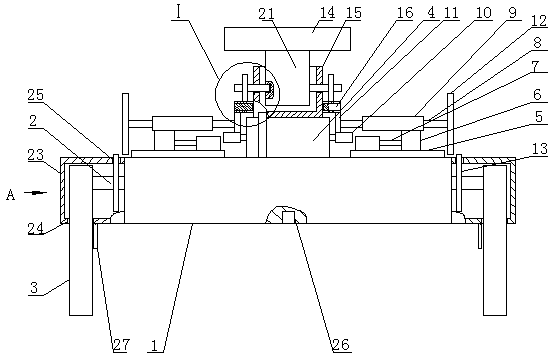
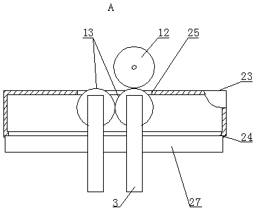
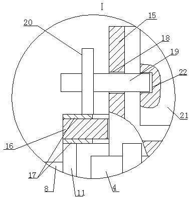
[0015]A wireless network data analysis device, as shown in the figure, includes a main body 1 and a mounting plate 14 of the wireless network data analysis device. The main body 1 is in the shape of a flat box. Tube 2, the heights of the four horizontal tubes 2 are the same, the horizontal tube 2 is perpendicular to the corresponding end of the ma...


PUM


Abstract

The invention provides a wireless network data analysis device which comprises a main body and a mounting board of the wireless network data analysis device. The main body is shaped like a flat box. Two horizontal tubes are arranged at the intermediate positions of the left and right ends of the main body. The heights of four horizontal tubes are the same. Each horizontal tube is perpendicular toan end part corresponding to the main body. One end of each horizontal tube is movably linked with an outer casing bearing of the main body, and the other end of the horizontal tube is provided with avertical antenna. One side of the upper end of each antenna is fixedly connected with the other end of a corresponding horizontal tube. A double output shaft motor is fixedly arranged in the middle of the top of the main body. The double output shaft motor is horizontal. Cross rails are symmetrically and fixedly arranged on left and right sides of the double output shaft motor at the top of the main body. The cross rails are parallel to the output shafts of the double output shaft motor. Sliders are arranged at the upper parts of the cross rails in a matched manner. According to the invention, rapid installation and disassembly of the main body are realized; the angle and intensity of signal transmitting and receiving of the device provided by the invention can be adjusted at any time byconveniently adjusting the angle of the antennas; and an optimal signal transmitting and receiving effect is realized.

Description

technical field [0001] The invention belongs to the field of wireless network security technical equipment, in particular to a wireless network data analysis equipment. Background technique [0002] Wireless networks include both data networks that allow users to establish long-distance wireless connections, as well as analysis technologies optimized for short-distance wireless connections. They are very similar to wired networks. The biggest difference lies in the difference in transmission media, using radio technology instead of network cables , and can back up each other with the wired network. Compared with the wired network, the wireless network environment has the real-time dynamic change of the network topology, the possibility of heterogeneous real-time mobile terminals, heterogeneous network transmission media, unclear targets for security or preventable objects, and few or no terminal monitoring management nodes. Security risks such as new features, such as: the ...

Claims


Application Information

Patent Timeline
Patent Type & Authority Patents(China)
IPC IPC(8): H01Q1/22H01Q3/08H05K5/02
CPCH01Q1/2291H01Q3/08H05K5/0217
Inventor 高耀锋
Owner 山西爱牡彼爱科技股份有限公司
Learn More