Lubrication system comprising a spindle and an aerosol dispenser

a technology of aerosol dispenser and lubrication system, which is applied in the direction of metal-working machine components, maintenance and safety accessories, metal-working apparatuses, etc., can solve the problems of increasing the consumption of lubricant and/or coolant and not being desired, and achieve the effect of improving the aerosol transpor

Inactive Publication Date: 2019-04-09
KNOLL MASCHENBAU
View PDF11 Cites 2 Cited by
  • Summary
  • Abstract
  • Description
  • Claims
  • Application Information

AI Technical Summary

Benefits of technology

[0011]It is the object of the present invention to propose a lubrication system, in particular, a single-duct minimum quantity lubrication system, having an aerosol generator and a spindle or motor spindle, which lubrication system improves the aerosol transport, in particular, the transport of lubricant particles and / or coolant particles above all inside the spindle or motor spindle.
[0012]Accordingly, a lubrication system according to the present invention is characterized in that the spindle tube is mounted in an electrically insulating manner on the rotary feedthrough and / or on the tool clamper and / or the spindle tube is produced from a material that is not electrically conductive, for example, plastics material or ceramic, and / or that the spindle tube and / or the duct is / are provided with at least one electrically insulating layer for coating the spindle tube and / or the duct in an electrically insulating manner. This shows that the transport of aerosol to the tool clamper is considerably improved as the aerosol or the aerosol particles is / are substantially electrically charged.

Problems solved by technology

On account of this, in the prior art aerosol particles or lubricant and / or coolant are deposited on the inner wall of the aerosol line and of the spindle tube, which is disadvantageous because the lubricant and / or coolant or the aerosol particles are not available (immediately or promptly) to the tool clamper and consequently for workpiece processing.
Thus, in the prior art, the deposited or separated lubricant and / or coolant then has to be compensated for by an additionally generated quantity of aerosol particles, which increases the consumption of lubricant and / or coolant and is not wanted.

Method used


Image

  • Lubrication system comprising a spindle and an aerosol dispenser
  • Lubrication system comprising a spindle and an aerosol dispenser
  • Lubrication system comprising a spindle and an aerosol dispenser

Examples


Embodiment Construction

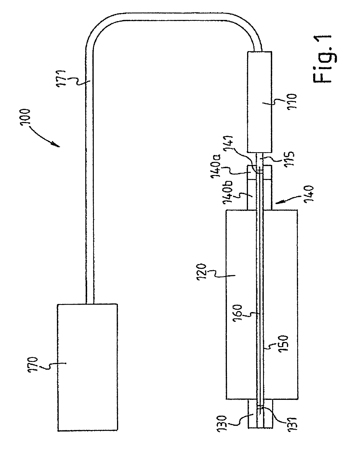
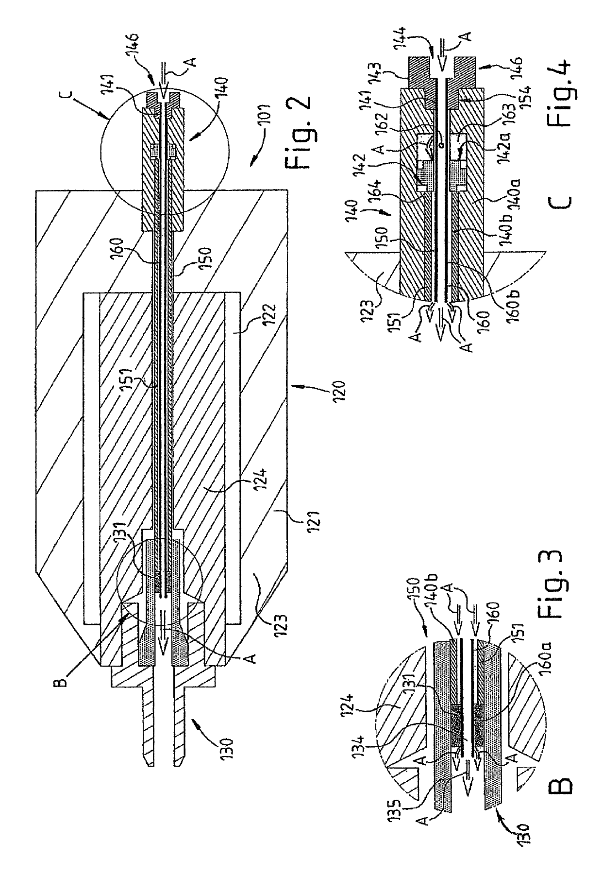
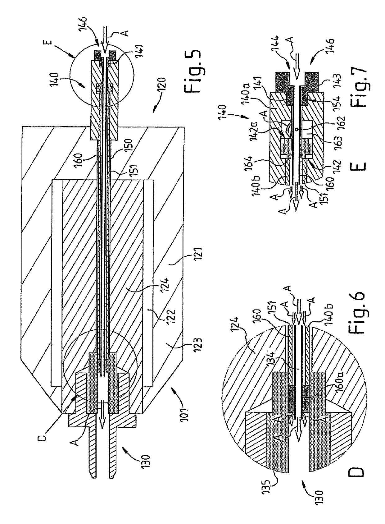
[0056]FIG. 1 shows a lubrication system 100, in particular, a so-called single-duct minimum quantity lubrication system 100 having an aerosol generator 110 for generating aerosol A, a spindle 120 driven by a motor, a tool clamper 130 arranged on the spindle 120 and a rotary feedthrough 140 arranged on the side of the spindle 120 located opposite the tool clamper 130 with a non-rotatably mounted, non-rotating portion 140a and a portion 140b which is entrained with the spindle 120. The tool clamper 130, the spindle 120 and the rotary feedthrough 140 are penetrated by a duct 150 which is connected to the aerosol generator 110 by means of a feed line 115.

[0057]A spindle tube 160, which is shown simply as a line in the schematic sketch according to FIG. 1, is arranged in the duct 150. The spindle tube 160 is non-rotatably mounted on the non-rotating portion 140a of the rotary feedthrough by way of a bearing 141 and extends through the spindle 120 in the direction of the tool clamper 130 ...


PUM


Abstract

Proposed is a lubrication system, in particular a single-duct minimum quantity lubrication system, having an aerosol generator, a spindle, a tool clamper arranged on the spindle and a rotary feedthrough arranged on the side of the spindle located opposite the tool clamper, the tool clamper, the spindle and the rotary feedthrough are penetrated by a duct, in the duct is arranged a spindle tube which improves the transport of aerosol, in particular the transport of lubricant particles and / or coolant particles, above all inside the spindle or motor spindle. Further, the spindle tube is mounted in the duct in an electrically insulating manner and / or in that the spindle tube is produced from a material that is not electrically conducting and / or in that the spindle tube and / or the duct is / are provided with at least one electrically insulating layer for coating the spindle tube and / or the duct in an electrically insulating manner.

Description

CROSS REFERENCE TO RELATED APPLICATIONS[0001]This application is a continuation of International Application No. PCT / EP2016 / 060821 filed May 13, 2016, which designated the United States, and claims the benefit under 35 USC § 119(a)-(d) of German Application No. 20 2015 102 484.3 filed May 13, 2015, the entireties of which are incorporated herein by reference.FIELD OF THE INVENTION[0002]The present invention relates to a lubrication system, in particular, a single-duct minimum quantity lubrication system, having an aerosol generator and a spindle.BACKGROUND OF THE INVENTION[0003]In a variety of technical working procedures when processing materials, for example, when machining materials, it is advantageous to provide lubrication and / or cooling at the processing point to increase process reliability in order, among other things, to ensure the perfect functioning of a tool and to increase its service life.[0004]In order, for example, to keep down the costs for the respective lubricant ...

Claims


Application Information

Patent Timeline
Patent Type & Authority Patents(United States)
IPC IPC(8): B23Q11/00B23Q11/10
CPCB23Q11/1015B23Q11/1076B23Q11/0046
Inventor AYGUN, TALIPAYGUN, YASAR
Owner KNOLL MASCHENBAU
Why Eureka
Try Eureka