
Extendable drilling tool

a drilling tool and extension technology, applied in the field of extension drilling tools, can solve the problems of increasing the length of the slots, reducing the space between the arm and the slot, and reducing the length of the body

Active Publication Date: 2019-04-09
DRILLSTAR INDS
View PDF9 Cites 0 Cited by
  • Summary
  • Abstract
  • Description
  • Claims
  • Application Information

AI Technical Summary

Benefits of technology

[0014]The presence of all of these ribs and grooves complicates the tool. According to another drawback, the fact of providing a reduced angle between the grooves and the longitudinal axis leads, on the one hand, to increasing the travel of the piston, and, consequently, to lengthening the body of the enlargement tool, and on the other hand, to increasing the longitudinal travel of the arms and therefore to increasing the length of the slots and to providing more considerable space between each slot and each arm. This considerable space can enable the accumulation of elements external to the tool that can lock the arms in extended position.
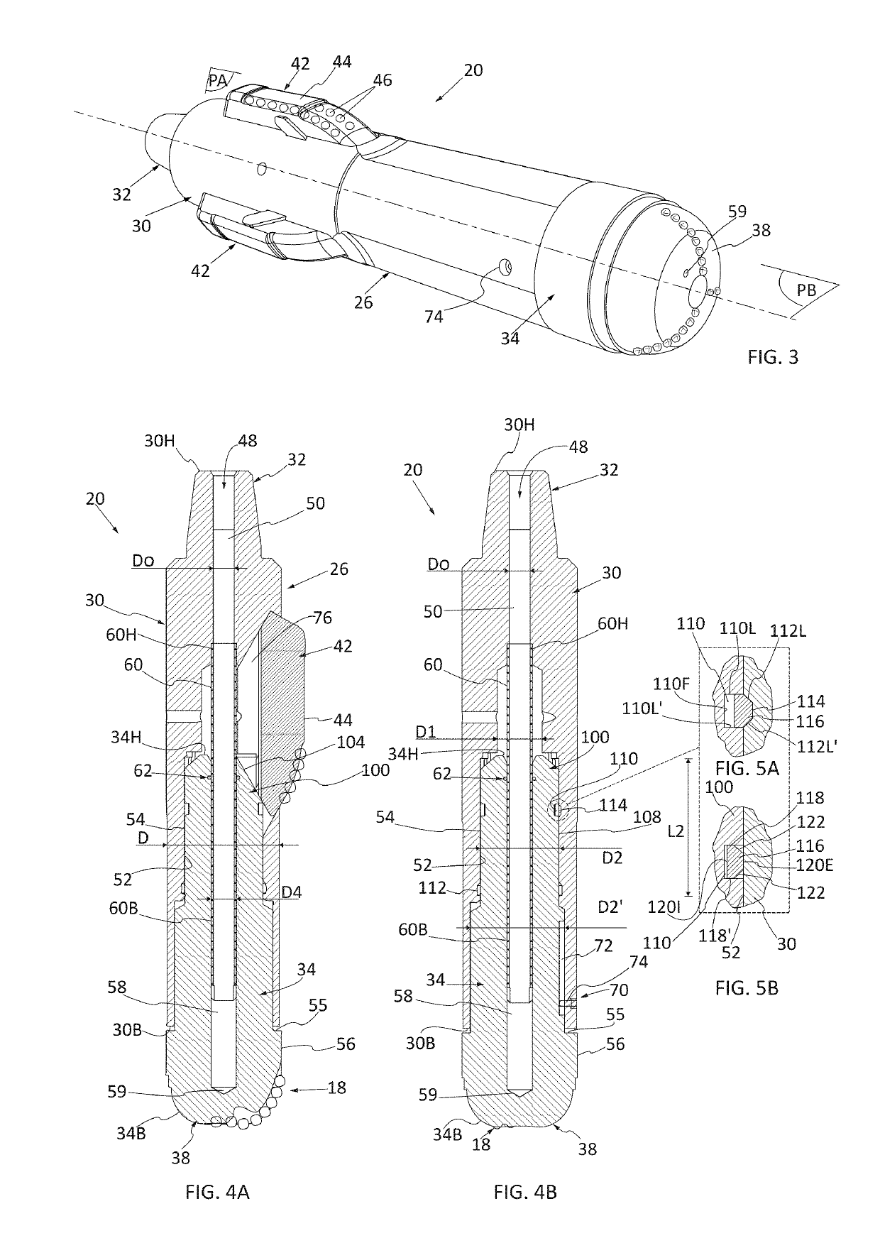
[0031]According to an embodiment, the piston comprises at least one channel, and the body comprises at least one channel that works with the channel of the piston when said piston is in the downstream position. In addition, the locking mechanism comprises an elastic ring configured to occupy a first state in which the elastic ring is placed astride in the channel of the piston and at least one channel of the body so as to immobilize in translation the piston relative to the body and a second state in which the elastic ring is accommodated only in the channel of the piston so as to make possible a translational movement of the piston relative to the body, the elastic ring having a tendency to be positioned in the first state because of its elasticity.

Problems solved by technology

The presence of all of these ribs and grooves complicates the tool.
According to another drawback, the fact of providing a reduced angle between the grooves and the longitudinal axis leads, on the one hand, to increasing the travel of the piston, and, consequently, to lengthening the body of the enlargement tool, and on the other hand, to increasing the longitudinal travel of the arms and therefore to increasing the length of the slots and to providing more considerable space between each slot and each arm.

Method used


Image

  • Extendable drilling tool
  • Extendable drilling tool
  • Extendable drilling tool

Examples


Embodiment Construction

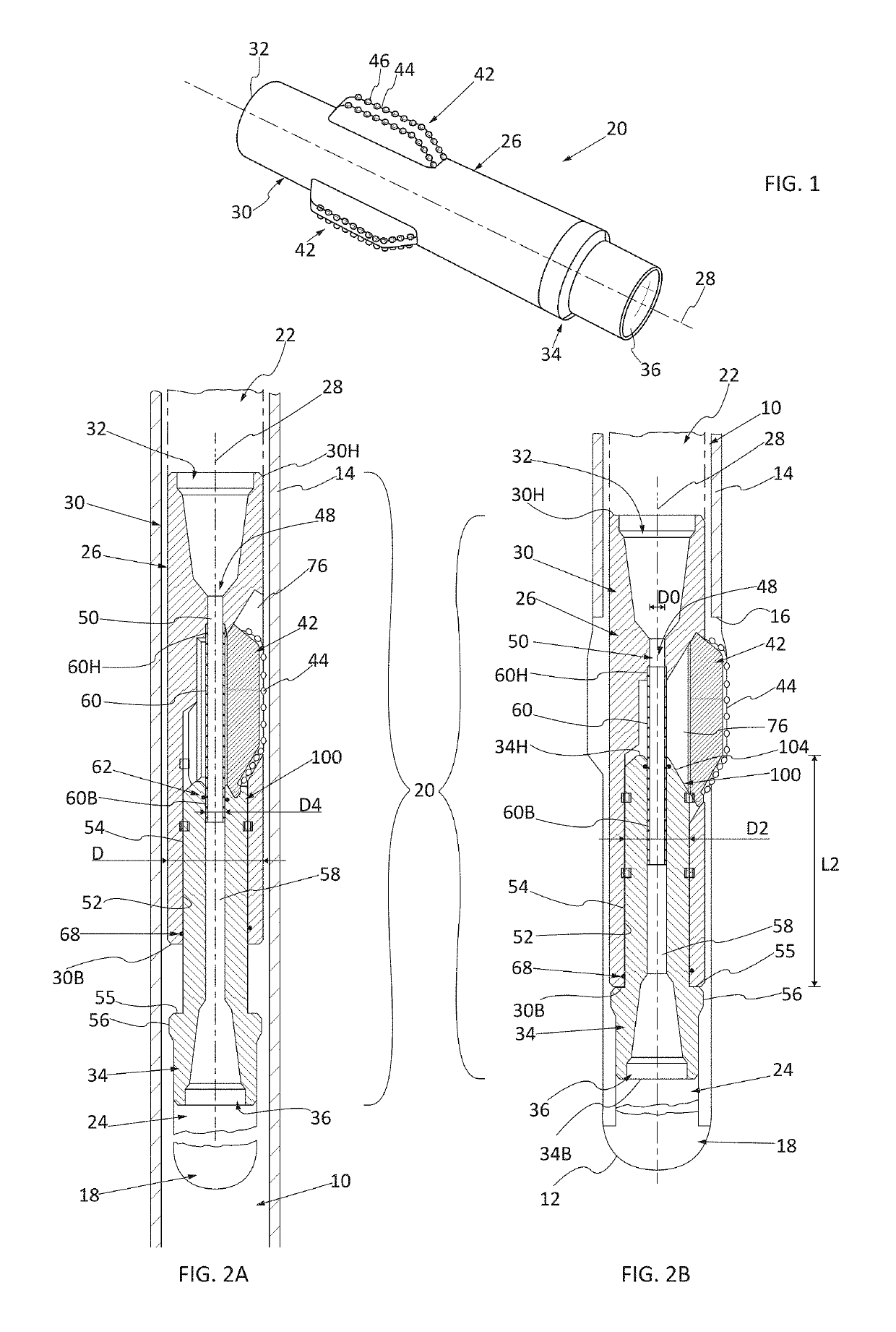
[0050]In FIGS. 2A, 2B, a drilling device has been shown that comprises a head tool 18, an extendable tool 20, an upper segment of rods 22 located above the extendable tool 20 that extends up to the surface, and a lower segment of rods 24 located under the extendable tool 20 and that connects to the head tool 18.

[0051]The head tool 18, the rod segments 22 and 24, as well as the other elements of the drilling device are not described further because they are known to a person skilled in the art.

[0052]The extendable tool 20 comprises a body 26 that has approximately a circular shape along a longitudinal axis 28.

[0053]The longitudinal axis is theoretically merged with the axis of the casing 14.

[0054]For the rest of the description, a longitudinal plane contains the longitudinal axis 28. A longitudinal direction is parallel to the longitudinal axis 28. A radial direction is secant and perpendicular to the longitudinal axis 28. A radial plane is a plane that is perpendicular to the longit...


PUM


Abstract

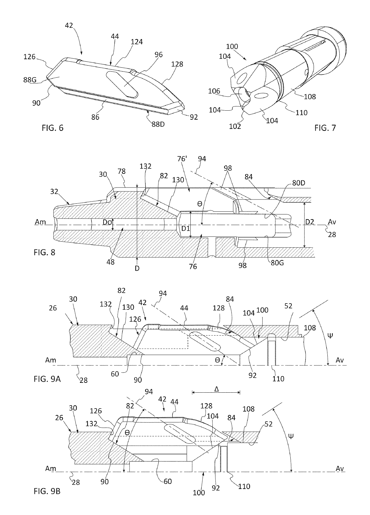
An extendable drilling tool, the extendable tool moving in a drilling direction and including a body with a longitudinal axis and at least one arm that is mobile relative to the body in a direction of movement that forms a first angle with the longitudinal axis that is non-zero, less than 45°, and open upstream according to the direction of drilling. The extendable tool includes a piston that is mobile in a direction parallel to the longitudinal axis, the piston being located downstream according to the direction of drilling relative to the arm, the piston including at least one bearing surface that works with at least one arm and that forms with the longitudinal axis a second angle that is non-zero, less than 90°, and open downstream according to the direction of drilling.

Description

FIELD OF THE INVENTION[0001]This invention relates to an extendable drilling tool. More particularly, the invention relates to a tool that makes it possible to enlarge a borehole.BACKGROUND OF THE INVENTION[0002]During drilling of an oil well, gas well, or other well, a casing comprising several segments arranged end-to-end is put into place on the walls of the borehole. The various segments are installed as drilling proceeds, the segments at the drilling bottom having to pass through those already installed.[0003]To maintain the largest possible passage section, the drilling device can comprise an enlargement tool that is generally positioned above a head tool that is designed to dig the bottom of the slot, such as a drill bit, for example.[0004]In a known way, an enlargement tool comprises a body whose cross-section is less than the diameter of the casing and that has a circular shape along a longitudinal axis that is merged with the axis of the drilling device. This body comprise...

Claims


Application Information

Patent Timeline
Patent Type & Authority Patents(United States)
IPC IPC(8): E21B10/32E21B7/28
CPCE21B10/32E21B10/322E21B7/28E21B10/26
Inventor IHLEIN, PATRICKSOUCHAL, RAPHAELBOUTELIER, JEAN-AIMECABE, CEDRIC
Owner DRILLSTAR INDS
Learn More