Eureka AIR delivers breakthrough ideas for toughest innovation challenges, trusted by R&D personnel around the world.

Relay device and relay system

a relay system and relay technology, applied in the field of relay devices and relay systems, can solve the problems of fault tolerance as the relay device is degraded, inconsistency may occur in the process of ring protocol, etc., and achieve the effect of improving the efficiency of the process in the devi

Inactive Publication Date: 2019-04-09
APRESIA SYST LTD
View PDF6 Cites 0 Cited by
  • Summary
  • Abstract
  • Description
  • Claims
  • Application Information

AI Technical Summary

Benefits of technology

[0004]The ring protocol typified by, for example, ITU-T G.8032 described in the Non-Patent Document 1 has been known. Also, as one mode of a relay device (L2 switch) which performs a process of a layer 2 (L2) of an OSI reference model, the chassis-type relay device described in the Patent Document 1 has been known. The chassis-type relay device is provided with a line card which transmits and receives a frame to and from an external device and a management card which manages an entire device including the line card in some cases. When a ring protocol is implemented on the chassis-type relay device like this, the efficiency of the process in the device can be improved by mounting a control unit of the ring protocol mainly in the management card.
[0005]Here, it is desirable that a redundancy configuration including a card in an active state and a card in a standby state is applied to the management card as described in the Patent Document 1 in order to improve the fault tolerance. In this case, for example, even when a fault occurs in a card [11] in an active state while the card [1] is executing a ring protocol, a card [2] in a standby state is changed to the active state in place of the card [1], so that the process of the ring protocol can be continuously performed.
[0012]The advantages obtained by representative embodiments in the present invention disclosed in the present application will be briefly described as follows. That is, it is possible to achieve the improvement in the fault tolerance.

Problems solved by technology

As a result, some errors may occur in the process of the ring protocol and there is fear that the fault tolerance as the relay device is degraded.
If the card [2] is changed to the active state in place of the card [1] in this state, the inconsistency may occur in the process of the ring protocol.

Method used


Image

  • Relay device and relay system
  • Relay device and relay system
  • Relay device and relay system

Examples


first embodiment

[0039]>

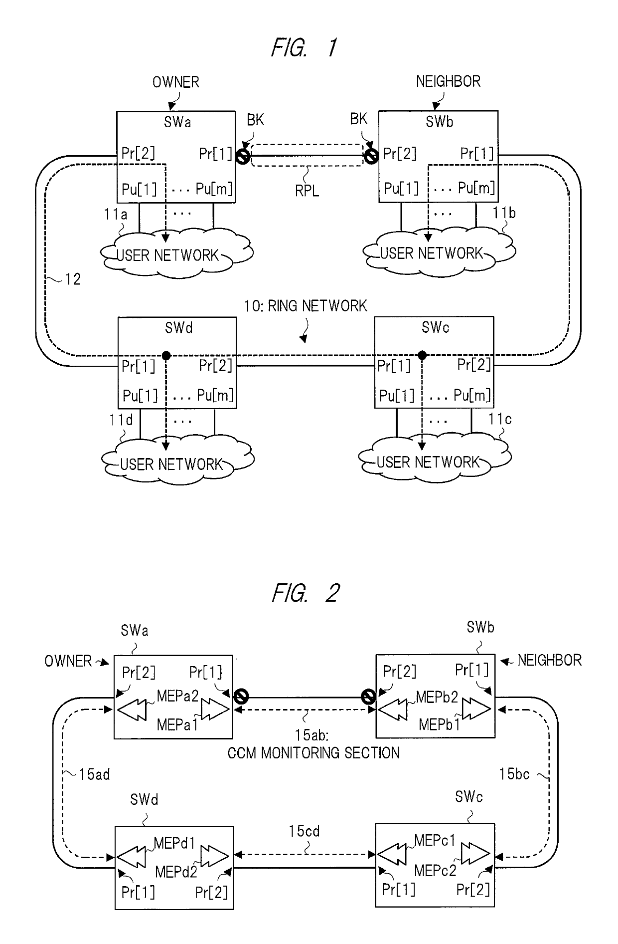
[0040]FIG. 1 is a schematic view showing a configuration example of a relay system and an operation example in the absence of fault according to the first embodiment of the present invention. The relay system shown in FIG. 1 includes a plurality of (here, four) relay devices SWa to SWd constituting a ring network 10. Each of the relay devices SWa to SWd is referred to also as a node. Each of the relay devices SWa to SWd has two ring ports Pr[1] and Pr[2] and m (m is an integer of 1 or more) user ports Pu[1] to Pu[m]. The number of relay devices constituting the ring network 10 is four in this example, but is not limited thereto and may be any number as long as it is two or larger.

[0041]The ring network 10 is controlled based on, for example, a ring protocol defined by ITU-T G.8032. In other words, each of the relay devices SWa to SWd is provided with various control functions based on the ring protocol. Each of the relay devices SWa to SWd is an L2 switch which performs the r...

second embodiment

[0168]>

[0169]FIG. 19 is a sequence diagram showing an example of a ring protocol operation in the occurrence of an active change in the relay device examined as a comparative example of the present invention. As described in FIG. 7, for example, each of the management cards MC1 and MC2 regularly communicates the ICCM frame with the line card LC. Here, the VID control instruction described in FIG. 9 and others can be stored in the ICCM frame by an interruption method only when the change or the like occurs in the instruction. Alternatively, it is also possible to always store the VID control instruction in the ICCM frame transmitted regularly regardless of the presence or absence of the change in the instruction.

[0170]In this case, even if the situation in which the ICCM frame cannot be received due to any cause at a certain moment (that is, non-reception of instruction) occurs, the line card LC can receive the instruction by the next ICCM frame transmitted regularly. In this case, h...


PUM


Abstract

A plurality of management cards including an active card and a standby card are provided. The active card determines open or block of a ring port in accordance with an event based on a ring protocol, issues an open instruction or a block instruction to a line card, and notifies a block factor in addition to the block instruction when issuing the block instruction. The line card controls open or block of the ring port in accordance with the open instruction or the block instruction and retains open / block information of the ring port and a block factor of the block state in a port management table. When the standby card is changed to the active card in accordance with a predetermined change instruction, it acquires the information retained in the port management table from the line card.

Description

CROSS-REFERENCE TO RELATED APPLICATION[0001]The present application claims priority from Japanese Patent Application No. 2016-018360 filed on Feb. 2, 2016, the content of which is hereby incorporated by reference into this application.TECHNICAL FIELD OF THE INVENTION[0002]The present invention relates to a relay device and a relay system, for example, a relay device having a redundancy configuration therein and a relay system to which a ring protocol is applied.BACKGROUND OF THE INVENTION[0003]For example, Japanese Patent Application Laid-Open Publication No. 2014-195147 (Patent Document 1) describes a scheme in which each of a plurality of line cards receives monitoring frames from two redundant management cards and selects one of these frames to transmit it to an outside of a device in a chassis-type network relay device. Also, ITU-T G.8032 / Y.1344 (February 2012) (Non-Patent Document 1) describes a ring protocol of a ring network based on ITU-T G.8032.SUMMARY OF THE INVENTION[0004...

Claims


Application Information

Patent Timeline
Patent Type & Authority Patents(United States)
IPC IPC(8): H04L12/437H04L12/937H04L12/42H04L69/40
CPCH04L12/437H04L2012/421H04L49/253H04L12/4604H04L69/40
Inventor YASUDA, MAKOTO
Owner APRESIA SYST LTD
Why Eureka
Eureka Blog
Learn More