Multi-mode transmitter with an antenna array for delivering wireless power and providing Wi-Fi access

Active Publication Date: 2019-04-16
ENERGOUS CORPORATION
View PDF986 Cites 56 Cited by
  • Summary
  • Abstract
  • Description
  • Claims
  • Application Information

AI Technical Summary

Benefits of technology

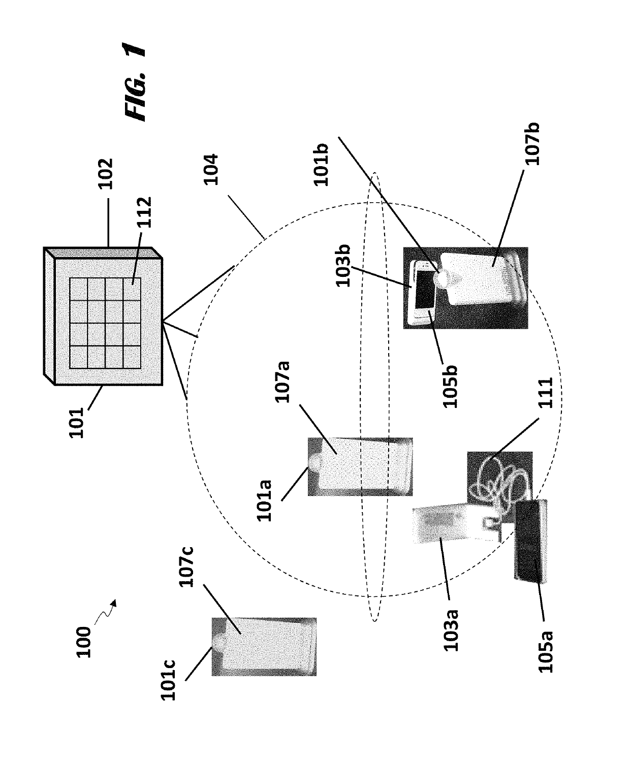
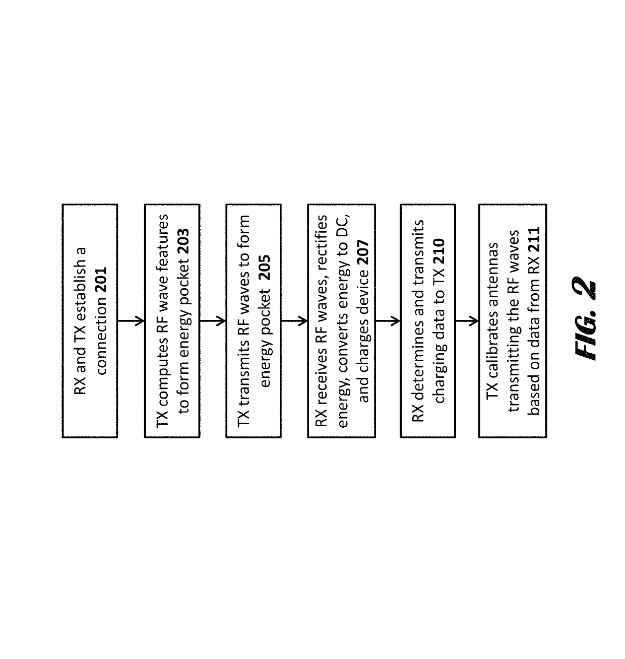
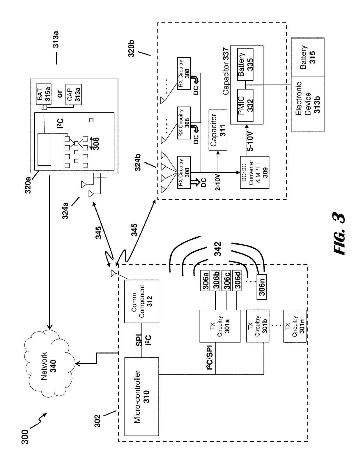
[0008]The embodiments described herein include a transmitter that transmits a power transmission signal (e.g., radio frequency (RF) signal waves) to create a three-dimensional pocket of energy. At least one receiver can be connected to or integrated into electronic devices and receive power from the pocket of energy. The transmitter can locate the at least one receiver in a three-dimensional space using a communication medium (e.g., Bluetooth technology). The transmitter gen

Problems solved by technology

The frequent use of these devices may require a significant amount of power, which may easily deplete the batteries attached to these devices.
Therefore, a user is frequently needed to plug in the device to a power source, and recharge such device.
Such an activity may be tedious and may represent a burden to users.
However, such an activity may render electronic devices inoperable during charging.
Solar-powered battery chargers are also known, however, solar cells are expensive, and a large array of solar cells may be required to charge a battery of any significant capacity.
Assuming that the transmitted signal has an efficient reception at three centimeters from the EM transmitte

Method used


Image

  • Multi-mode transmitter with an antenna array for delivering wireless power and providing Wi-Fi access
  • Multi-mode transmitter with an antenna array for delivering wireless power and providing Wi-Fi access
  • Multi-mode transmitter with an antenna array for delivering wireless power and providing Wi-Fi access

Examples


Example

[0047]The present disclosure is here described in detail with reference to embodiments illustrated in the drawings, which form a part here. Other embodiments may be used and / or other changes may be made without departing from the spirit or scope of the present disclosure. The illustrative embodiments described in the detailed description are not meant to be limiting of the subject matter presented here. Furthermore, the various components and embodiments described herein may be combined to form additional embodiments not expressly described, without departing from the spirit or scope of the invention.

[0048]Reference will now be made to the exemplary embodiments illustrated in the drawings, and specific language will be used here to describe the same. It will nevertheless be understood that no limitation of the scope of the invention is thereby intended. Alterations and further modifications of the inventive features illustrated here, and additional applications of the principles of ...


PUM


Abstract

A method for wireless power transmission is provided. The method comprising emitting, by a first antenna element of a transmitter, a first signal comprising a plurality of wireless power waves establishing a pocket of energy. The method further comprising emitting, by a second antenna element of the transmitter, a second signal different from the first signal. The second signal provides Wi-Fi access.

Description

CROSS-REFERENCE TO RELATED APPLICATIONS[0001]This application is a continuation-in-part of U.S. patent application Ser. No. 13 / 926,055, filed Jun. 25, 2013, which is herein fully incorporated by reference in its entirety for all purposes.[0002]This application relates to U.S. Non-Provisional patent application Ser. No. 13 / 891,430, filed May 10, 2013, entitled “Methodology For Pocket-forming;” U.S. Non-Provisional patent application Ser. No. 13 / 925,469, filed Jun. 24, 2013, entitled “Methodology for Multiple Pocket-Forming;” U.S. Non-Provisional patent application Ser. No. 13 / 946,082, filed Jul. 19, 2013, entitled “Method for 3 Dimensional Pocket-forming;” U.S. Non-Provisional patent application Ser. No. 13 / 891,399, filed May 10, 2013, entitled “Receivers for Wireless Power Transmission;” U.S. Non-Provisional patent application Ser. No. 13 / 891,445, filed May 10, 2013, entitled “Transmitters for Wireless Power Transmission;” U.S. Non-Provisional patent application Ser. No. 14 / 272,039,...

Claims


Application Information

Patent Timeline
IPC IPC(8): H02J5/00H04W84/12
CPCH02J5/005H04W84/12H02J50/20H02J50/80H02J7/00034H02J50/402
Inventor LEABMAN, MICHAEL A.BREWER, GREGORY SCOTT
Owner ENERGOUS CORPORATION
Why Eureka
Try Eureka