Gard-U door safety system

a door safety and security technology, applied in the field of locks, can solve the problems of unattended children, unfavorable opening of doors, and uncontrollable opening of doors, and achieve the effects of convenient and rapid installation, easy manipulation of the door control, and avoiding production

Active Publication Date: 2019-04-23
SCHULZ VICTOR
View PDF19 Cites 2 Cited by
  • Summary
  • Abstract
  • Description
  • Claims
  • Application Information

AI Technical Summary

Benefits of technology

[0020]A first object of the invention is to provide rapid and intuitive enablement to selectively either secure a pre-existing door lock or alternatively to block the door lock from activating. A second object of the invention is to provide an apparatus that is mounted as a replacement for existing strike plates, to thereby fit nearly every door through a direct and low cost door strike plate replacement, to thereby allow the door to be fully opened or closed, to thereby permit the existing door lock to be operated with a key, to thereby permit easy and rapid installation using common tools such as a screwdriver and not require any destructive alteration of the existing door or door frame, and to thereby be used repeatedly while avoiding the production of undesirable forces on the door or door frame that could undesirably damage the door or frame. Another object of the present invention is that the geometry of the components used in the apparatus are independent of whether a door opens in or out, and is right or left handed, so that a simple reorientation of one component relative to another is all that is required to accommodate the particular door. A further object of the invention is to enable the apparatus to be actuated irrespective of whether the door is open or closed. Yet another object of the present invention is to provide an apparatus that will operate in a stable and predictable manner relatively independent of the torque used on fasteners during installation of the apparatus, and subsequent thereto which will operate in a stable and predictable manner reasonably independent of the level of torque in the same fasteners. An even further object of the invention is the provision of a door safety apparatus that will be easily manipulated to control the door lock by nearly all persons, even when the person is severely panicked by circumstances of the moment. An additional object of the invention is for the apparatus to be maintenance-free, durable and dependable, preferably capable of being exposed to the elements for use with either exterior or interior doors and further having ensured presence, so that the apparatus cannot be lost or misplaced.

Problems solved by technology

Unfortunately, in that same household, a breeze coming through an open window might undesirably blow a door shut, locking the person out of a space.
In other similar situations, a child in the house might accidentally shut a door, leaving the child unattended in what might be a dangerous space and the parent blocked from access without causing severe damage to the door or lock.
However, in the event of an emergency such as an armed assailant in the building, the keys may not be readily accessible.
Consequently, large numbers of persons in such rooms may be exposed to the assailant, where a simple locking apparatus not requiring the use of a key would instead protect them from the assailant.
In another instance, when a person wishes to step out of their apartment or hotel room, perhaps to flag down a service or delivery person, they may not always remember or have ready access to the room key.
While each of these may provide a desired utility, they each also require destructive alteration of the door face, which is highly undesirable.
While this and similar door blocking devices can be very effective, the force of the door swinging shut against the relatively small blocking device can damage the blocking device or the door frame.
Unfortunately, each of these apparatus suffers from several undesirable limitations.
If the screw is tightened down too much, the plate will not be free to move between locked and unlocked positions.
Furthermore, the Mossotti et al device relies upon a vertical position for the inactive state or door-locked position, a position which is not easily set or maintained.

Method used


Image

  • Gard-U door safety system
  • Gard-U door safety system

Examples


Embodiment Construction

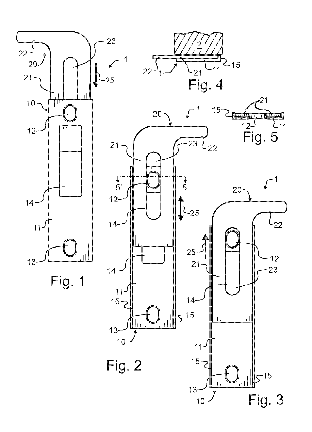
[0025]Manifested in the preferred and alternative embodiments, the present invention provides a sliding latch that affixes to a door frame as a replacement for the existing strike plate, that can be installed using a screwdriver, and that is readily operated to switch a door from an unlocked state to a locked state in a crisis by nearly all persons.

[0026]In a first preferred embodiment of the invention illustrated in FIGS. 1-5, a sliding latch 1 is comprised of only two components: a strike plate 10, and sliding latch cover 20 that reciprocates within strike plate 10. Strike plate 10 has a body member 11 through which a pair of screw holes 12, 13 and a bolt and latch bolt hole 14 are formed. This general geometry is preferably very similar in the front elevational view outline of FIG. 1 to that of prior art strike plates, to ensure the compatibility of first preferred embodiment sliding latch 1 with nearly all doors. However, as best illustrated in FIG. 4, a pair of raised edges 15 ...


PUM


Abstract

A sliding latch replaces a prior art door strike plate. The sliding latch has two components, a strike plate and a sliding latch cover reciprocal within the strike plate. A handle protrudes from the sliding latch cover sufficiently to extend beyond a closed door and door frame, to permit the handle to be manually grasped and lifted in a crisis. When the sliding latch cover is thus elevated, it no longer blocks the door bolt, allowing the bolt to extend farther and engage with the strike plate and extend into the door jamb, locking the door. One of the strike plate mounting screw holes is preferably drawn slightly out of the primary plane of the strike plate toward the jamb, and a pair of elevated distally located edges run longitudinally along the strike plate. The drawn screw hole and raised edges guide and limit motion of the sliding latch cover.

Description

CROSS REFERENCE TO RELATED APPLICATIONS[0001]The present application claims the benefit of United States provisional patent application 62 / 574,081 filed Oct. 18, 2017 of like title and inventorship, the teachings and entire contents which are incorporated herein by reference.BACKGROUND OF THE INVENTION1. Field of the Invention[0002]The present invention pertains generally to locks, and more particularly to a safety device that selectively allows or blocks a door from locking.2. Description of the Related Art[0003]Buildings have a number of openings through both interior and exterior walls provided for various distinct purposes. A number of these openings are for the mechanical systems such as heating, ventilating, and air conditioning. Most of these are too small for a person to pass through, and will typically be provided with some type of secured covering. Other openings such as windows and doors are provided for the convenience, safety, or access of the building occupants. In con...

Claims


Application Information

Patent Timeline
Patent Type & Authority Patents(United States)
IPC IPC(8): E05B17/00E05B63/18E05B17/20E05B15/02
CPCE05B17/005E05B15/0205E05B17/2038E05B63/185
Inventor SCHULZ, VICTOR
Owner SCHULZ VICTOR
Why Eureka
Try Eureka