Raintight Electrical Conduit Coupling and Connector

a technology of electrical conduits and connectors, applied in the direction of electrical apparatus, etc., can solve the problems of improper reassembling, subsequent leakage, awkward and time-consuming sequence, etc., and achieve the effect of enhancing the stability of the engagement, rapid and easy installation, and rapid installation

Active Publication Date: 2021-04-01
CREWL GLENN
View PDF0 Cites 0 Cited by
  • Summary
  • Abstract
  • Description
  • Claims
  • Application Information

AI Technical Summary

Benefits of technology

[0020]The cylindrical sleeve may have an exterior surface proximate to the first axial extremity that includes first and second peripheral ribs extending around the entire circumferential extent of the cylindrical sleeve. The first generally cylindrical clamp may have an inboard section and an outboard section, the inboard section of the first generally cylindrical clamp being dimensioned and configured for encircling the first axial extremity of the cylindrical sleeve being dimensioned and configured for nesting engagement with the first and second peripheral ribs whereby the stability of the engagement is enhanced.
[0021]It is an object of the present invention to provide embodiments that are raintight and can be installed rapidly and easily without awkward motions.
[0022]It is another object of the present invention to provide a coupling or connector that can very rapidly be installed, for example, with an electric screwdriver.

Problems solved by technology

The complications inherent in this sequence are both awkward and time consuming.
Still another issue with known compression fittings is that in the event of disassembly of the coupling, the required seal is often improperly reassembled leading to subsequent leakage.

Method used


Image

  • Raintight Electrical Conduit Coupling and Connector
  • Raintight Electrical Conduit Coupling and Connector
  • Raintight Electrical Conduit Coupling and Connector

Examples


Embodiment Construction

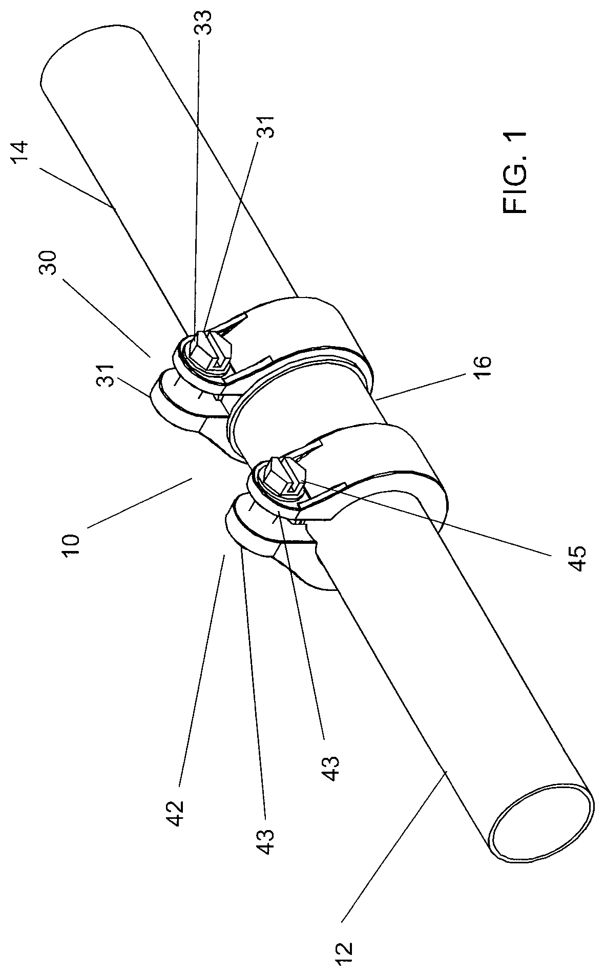
[0038]Referring now to FIGS. 1-8 there is shown a coupling 10 in accordance with one form of the present invention. Couplings in accordance with the present invention will ordinarily utilize attachment means in accordance with the present invention on each end of the coupling. Connectors in accordance with the present invention utilize only one attachment means in accordance with the present invention at one end thereof. More specifically, connectors, for example, the other end of the connector may use a lock nut on a threaded part of the connector at the other end.

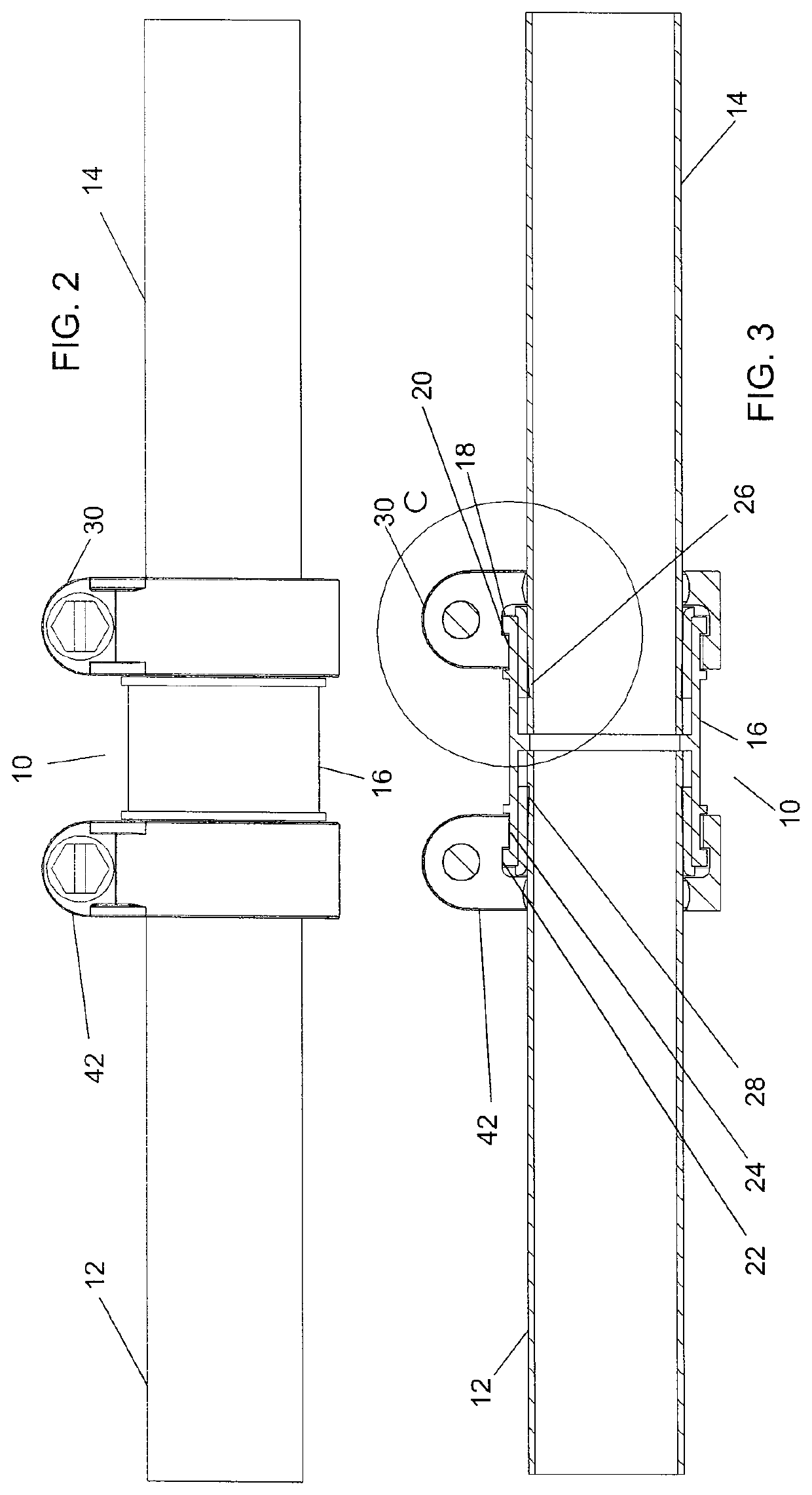
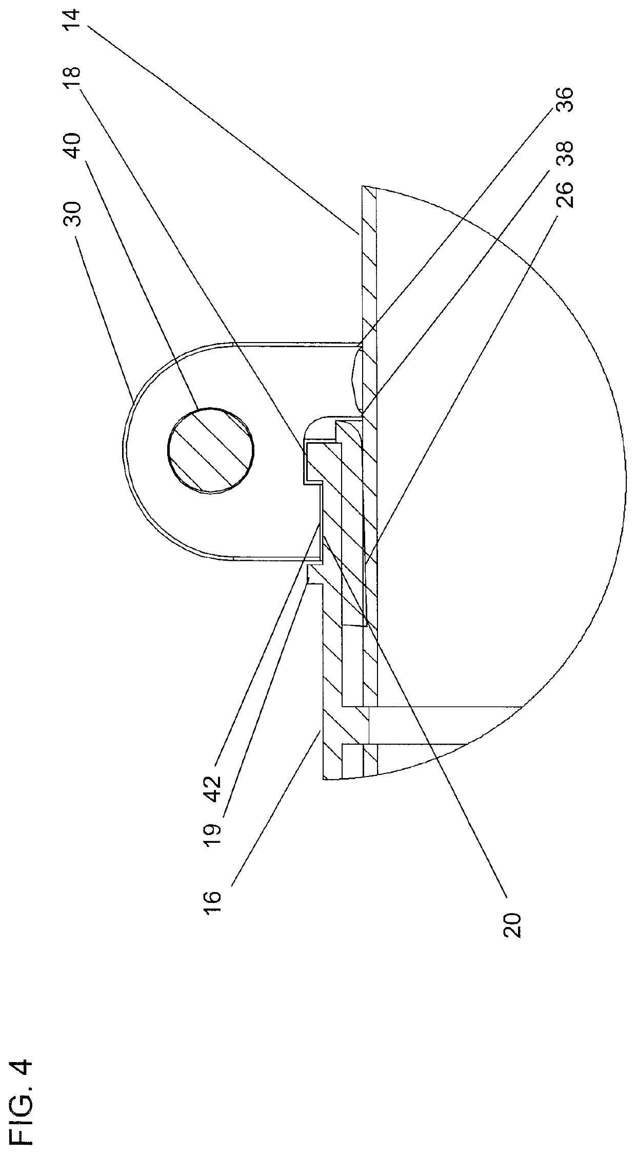
[0039]The coupling 10 for joining respective axial extremities of associated first and second axial sections of electrical conduit 12, 14 includes a cylindrical sleeve or body 16 having an interior surface and an exterior surface as well as a first axial extremity and a second axial extremity and a geometric axis. As best seen in FIGS. 3 and 4 the cylindrical sleeve 16 has an exterior surface proximate to the first axial ...


PUM


Abstract

A connector for joining respective axial extremities of associated first and second axial sections of electrical conduit which includes a cylindrical sleeve that has an interior surface and an exterior surface as well as a first axial extremity and a second axial extremity and a geometric axis. The cylindrical sleeve has an exterior surface proximate to the first axial extremity that includes a first peripheral rib extending around the entire circumferential extent of the exterior surface. The first peripheral rib has an outside diameter that is greater than the diameter of the cylindrical sleeve proximate to the first axial extremity. The cylindrical sleeve has an exterior surface proximate to the second axial extremity that includes a second peripheral rib extending around the entire circumferential extent of the exterior surface, the rib has an outside diameter is greater than the diameter of the cylindrical sleeve proximate to the second axial extremity.

Description

TECHNICAL FIELD[0001]The present invention is generally directed to electrical power distribution. More particularly, the present invention is directed to conduit systems. Even more particularly, the present invention is directed to couplings and connectors for conduit systems.[0002]The term “raintight” is a term of the art indicative of connectors and couplings that are liquid-tight tight in normal use. Some embodiments of the present invention are suitable for liquid-tight applications. Other embodiments eliminate a seal while retaining the advantages of quickly and easily achieving a connection where the ambient does have not have liquid in the ambient. Typically, dry indoor applications do not require the seal.[0003]Customarily in the art the term “connector” refers to apparatus for connecting, for example, 2 pieces of conduit and the term “coupling” refers to apparatus for connecting, for example, a conduit to a box. Since the present invention may be utilized in the constructi...

Claims


Application Information

Patent Timeline
Patent Type & Authority Applications(United States)
IPC IPC(8): H02G3/06H02G3/08
CPCH02G3/0666H02G3/088H02G3/0683
Inventor CREWL, GLENN
Owner CREWL GLENN
Why Eureka
Try Eureka