
Image forming apparatus, image data transmission method, and computer program

a technology of image data and forming apparatus, applied in the field of image data transmission methods, can solve the problems of data not being transmitted to a target destination, image forming apparatus cannot access the address book, etc., and achieve the effect of transmitting image data

Active Publication Date: 2019-04-23
KONICA MINOLTA INC
View PDF13 Cites 0 Cited by
  • Summary
  • Abstract
  • Description
  • Claims
  • Application Information

AI Technical Summary

Benefits of technology

The patent aims to make it easier for users to transmit image data from their image forming apparatus to a destination when they do not have access to their server's address book. The technical effect of this invention is to simplify the process of sharing images between devices.

Problems solved by technology

However, any malfunction may cause a case where the image forming apparatus cannot access the address book.
However, according to the traditional method, when an access to the address book managed by the server is not available, data cannot be transmitted to a target destination.

Method used


Image

  • Image forming apparatus, image data transmission method, and computer program
  • Image forming apparatus, image data transmission method, and computer program
  • Image forming apparatus, image data transmission method, and computer program

Examples


Embodiment Construction

[0038]Hereinafter, an embodiment of the present invention will be described with reference to the drawings. However, the scope of the invention is not limited to the illustrated examples.

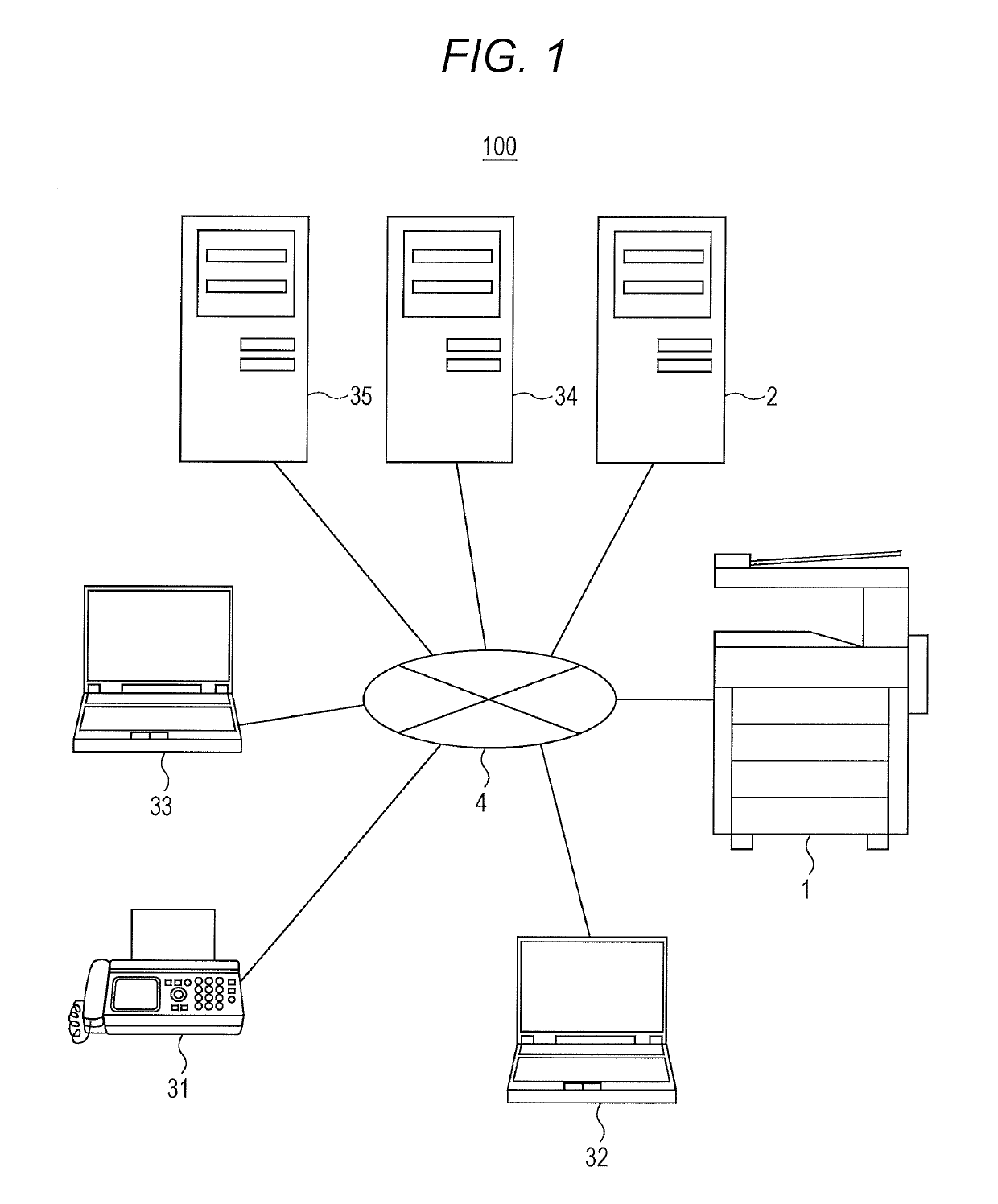
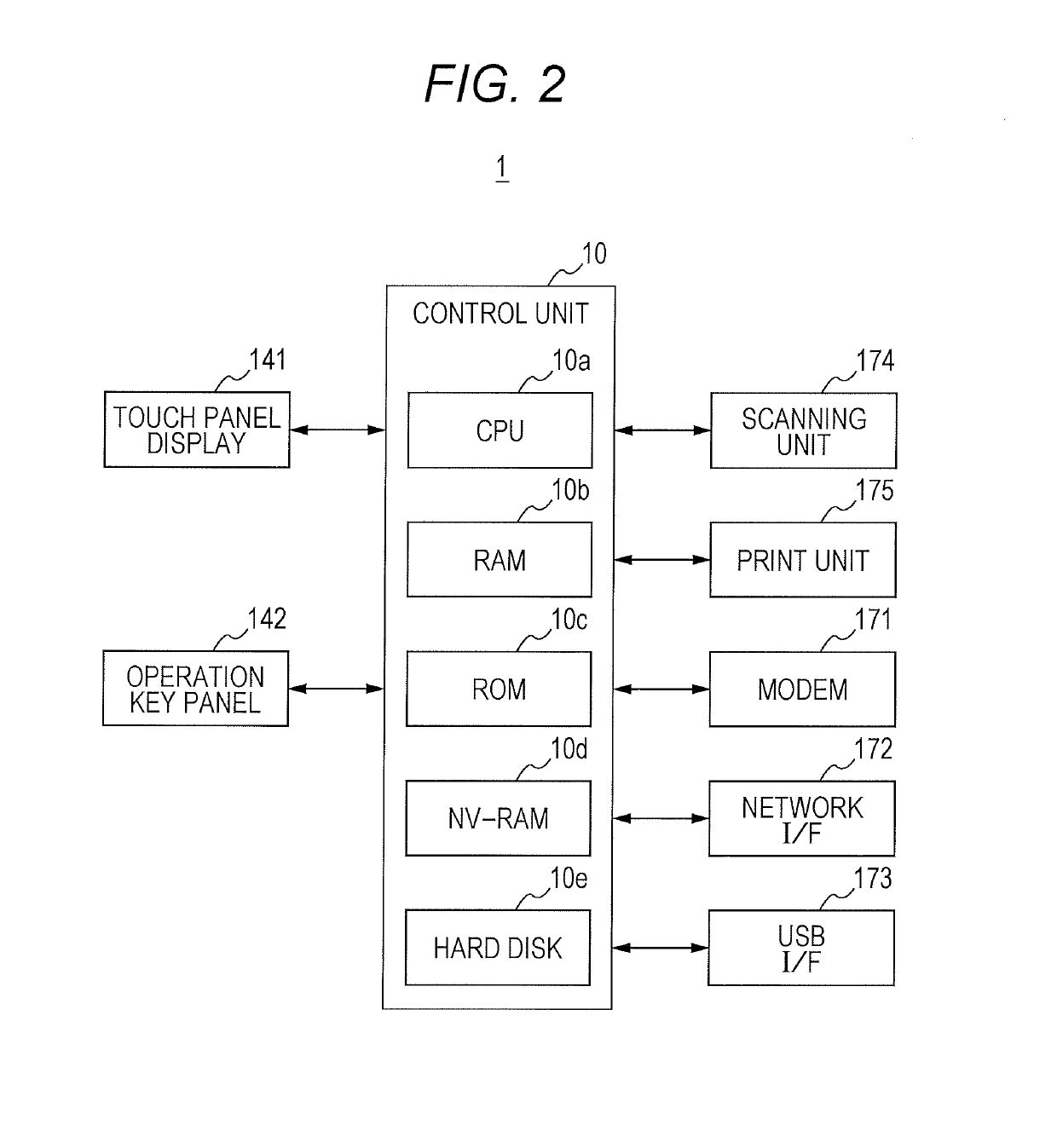
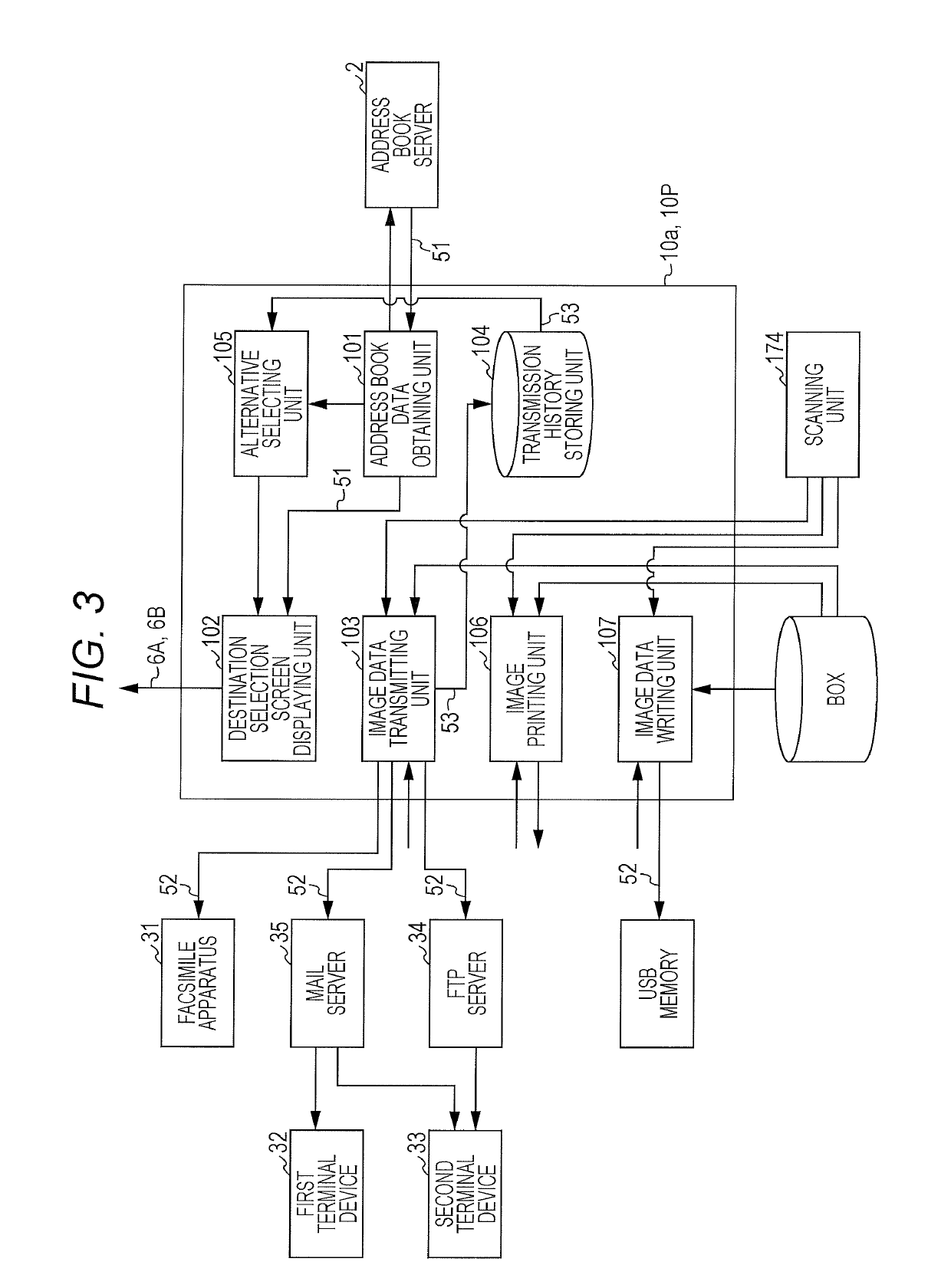
[0039]FIG. 1 is a diagram of an entire exemplary structure of an image transmission / reception system 100. FIG. 2 is a diagram of an exemplary hardware configuration of an image forming apparatus 1. FIG. 3 is a diagram of an exemplary functional configuration of the image forming apparatus 1.

[0040]As illustrated in FIG. 1, the image transmission / reception system 100 includes the image forming apparatus 1, an address book server 2, a facsimile apparatus 31, a first terminal device 32, a second terminal device 33, a file server 34, a mail server 35, a communication line 4, and the like.

[0041]The image forming apparatus 1 can communicate with the address book server 2, the facsimile apparatus 31, the first terminal device 32, the second terminal device 33, and the file server 34 via the communication li...


PUM


Abstract

An image forming apparatus includes: a reception unit configured to receive identifiers for communication of respective destinations from a first server; a display unit configured to display a screen to make an user select any one of the identifiers as an address of image data; and a transmission unit configured to transmit the image data to the selected identifier when any one of the identifiers has been selected and to transmit the image data to a transmission device for storing the identifier or a second server from which the transmission device downloads the data when the identifier is not received.

Description

[0001]The entire disclosure of Japanese Patent Application No. 2015-114049 filed on Jun. 4, 2015 including description, claims, drawings, and abstract are incorporated herein by reference in its entirety.BACKGROUND OF THE INVENTION[0002]Field of the Invention[0003]The present invention relates to a technique for transmitting image data from an image forming apparatus.[0004]Description of the Related Art[0005]An image forming apparatus has been widely used for integrating functions such as copy, network print, fax, scan, and box. The image forming apparatus is referred to as a “combined machine” or a “multi function peripherals (MFP)”.[0006]In addition, in recent years, various functions for transmitting data of an image to an external device such as a function for transmitting an email and a function for uploading data to an external server have been provided in the image forming apparatus.[0007]In this way, in recent years, the image forming apparatus can transmit the data of the i...

Claims


Application Information

Patent Timeline
Patent Type & Authority Patents(United States)
IPC IPC(8): G06F3/12H04N1/00H04L12/58
CPCH04N1/00095H04L51/28H04N1/00244H04N1/00411H04L51/10H04N1/00236H04N1/32037H04L51/48
Inventor SUGIYAMA, TAKANOBUOIKAWA, TAKASHIKITAGUCHI, TATSUYAIWAOKA, SHUMPEI
Owner KONICA MINOLTA INC
Learn More