Image processing apparatus and image processing method

a technology of image processing and image data, applied in the field of image processing apparatus and image processing method, can solve the problems of image degradation, differences in reproducibility and readability, and differences in portions, so as to prevent degradation of the output quality of image data

Inactive Publication Date: 2013-02-26
CANON KK
View PDF13 Cites 5 Cited by
  • Summary
  • Abstract
  • Description
  • Claims
  • Application Information

AI Technical Summary

Benefits of technology

[0009]More specifically, in the present invention, an area whose object type is a character or a line drawing is specified in image data, a spatial frequency characteristic of image data in the area is converted, and the image data is smoothened. Doing this enables providing an image processing apparatus and an image processing method that can output line drawings or characters that have been edge-emphasized, without the characters or line drawings being thinned down in comparison to line drawings or characters that have not been edge-emphasized.
[0012]The above aspect of the present invention enables outputting a line drawing or character that has been edge-emphasized, without the character or line drawing being thinned down in comparison to a line drawing or character that has not been edge-emphasized, thereby preventing degradation in the output quality of image data that has been filed.

Problems solved by technology

However, there are cases in which image processing differs depending on the type of MFP, and therefore if a MFP prints or files image data that has been digitized by a different type of MFP, it is possible for image degradation to occur.
However, when an output character image from an apparatus having such a function is compared to an output character image from an apparatus that does not have such a function, there are cases in which there are differences in portions other than the improved portion as well.
This leads to differences in the reproducibility and readability of characters in the filed image data, and can reduce the value of the filed document.

Method used


Image

  • Image processing apparatus and image processing method
  • Image processing apparatus and image processing method
  • Image processing apparatus and image processing method

Examples


embodiment 1

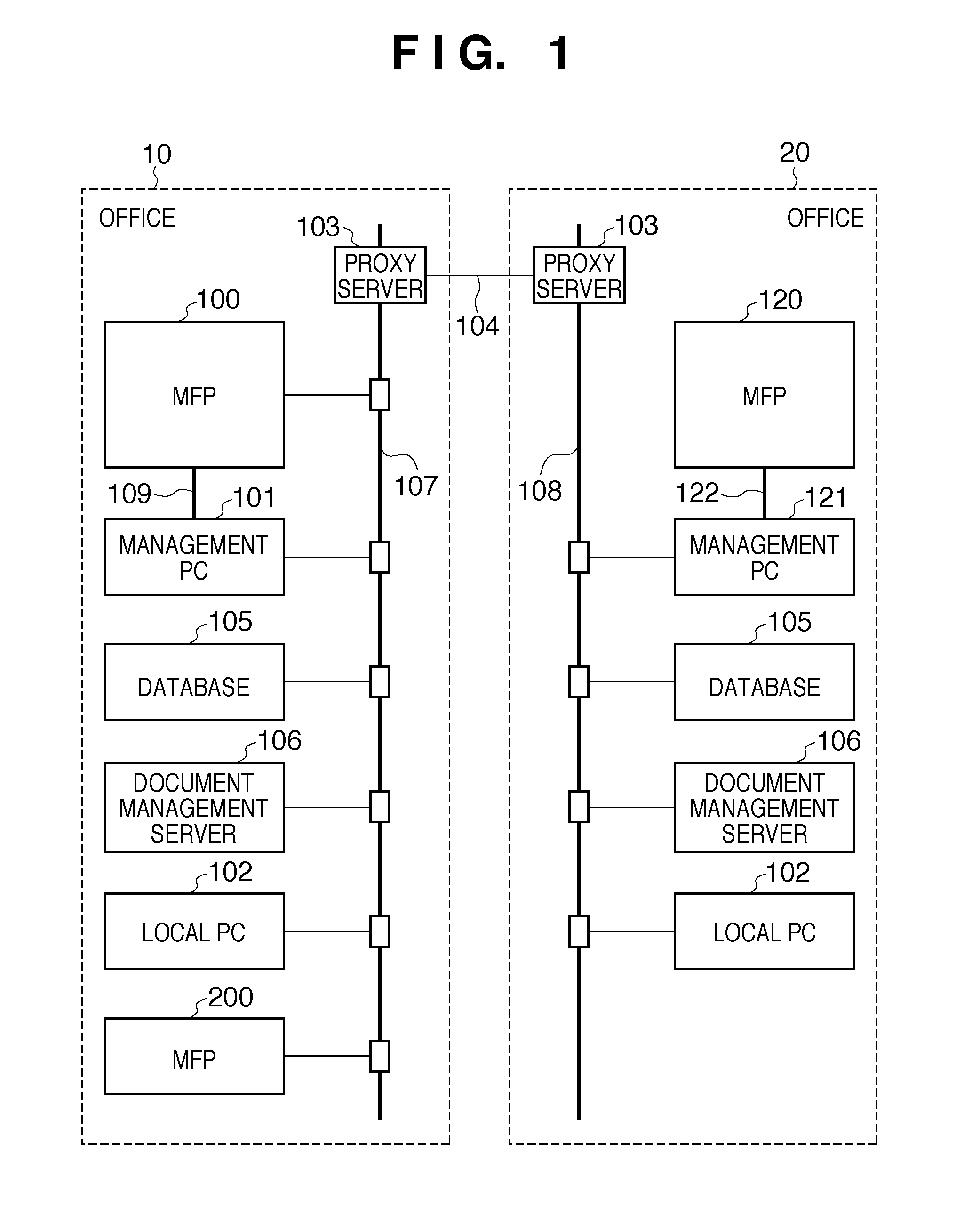
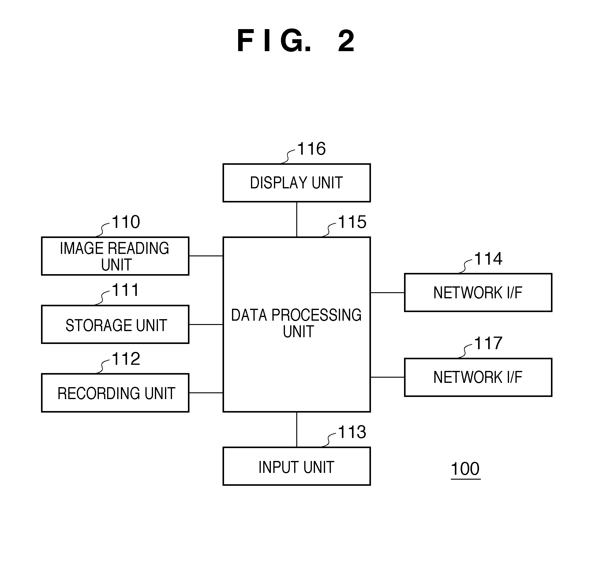
[0039]Next is a description of Embodiment 1 of an image processing method according to the present invention with reference to the drawings. FIG. 1 is a block diagram showing an image processing system according to the present invention, and FIG. 2 is a block diagram showing an MFP in FIG. 1.

[0040]Image Processing System

[0041]In FIG. 1, the image processing system according to the present invention is used in an environment in which an office 10 provided with a LAN 107 is connected via the Internet 104 to an office 20 provided with a LAN 108.

[0042]Connected to the LAN 107 are a multifunction peripheral (MFP) 100 that is a recording apparatus, a management PC 101 that controls the MFP 100, a local PC 102, a document management server 106, and a database 105 for the document management server 106.

[0043]Connected to the LAN 108 are an MFP 120 that is a recording apparatus, a management PC 121 that controls the MFP 120, a document management server 106, and a database 105 for the docume...

embodiment 2

[0141]In Embodiment 1, the binarizing unit 2905 performs a binarizing process using a fixed threshold value, but Embodiment 2 describes a case in which a variable threshold value is used.

[0142]FIG. 12 is a diagram showing such a processing structure. The processing structure shown in FIG. 12 is substantially the same as in FIG. 7 that is described in Embodiment 1. There are two differences in the processing, namely that a threshold value calculation unit 3404 has been added, and the binarizing unit 2905 that realizes the binarizing process using a fixed threshold value has been replaced with a binarizing unit 3405 that realizes the binarizing process using a variable threshold calculated by the threshold value calculation unit 3404.

[0143]The threshold value calculation unit 3404 uses a memory used by the MTF correction unit 2904, and in the exemplary case in which the MTF correction is a 5×5 spatial filter, the threshold value calculation unit 3404 uses the 5×5 area and calculates a...

embodiment 3

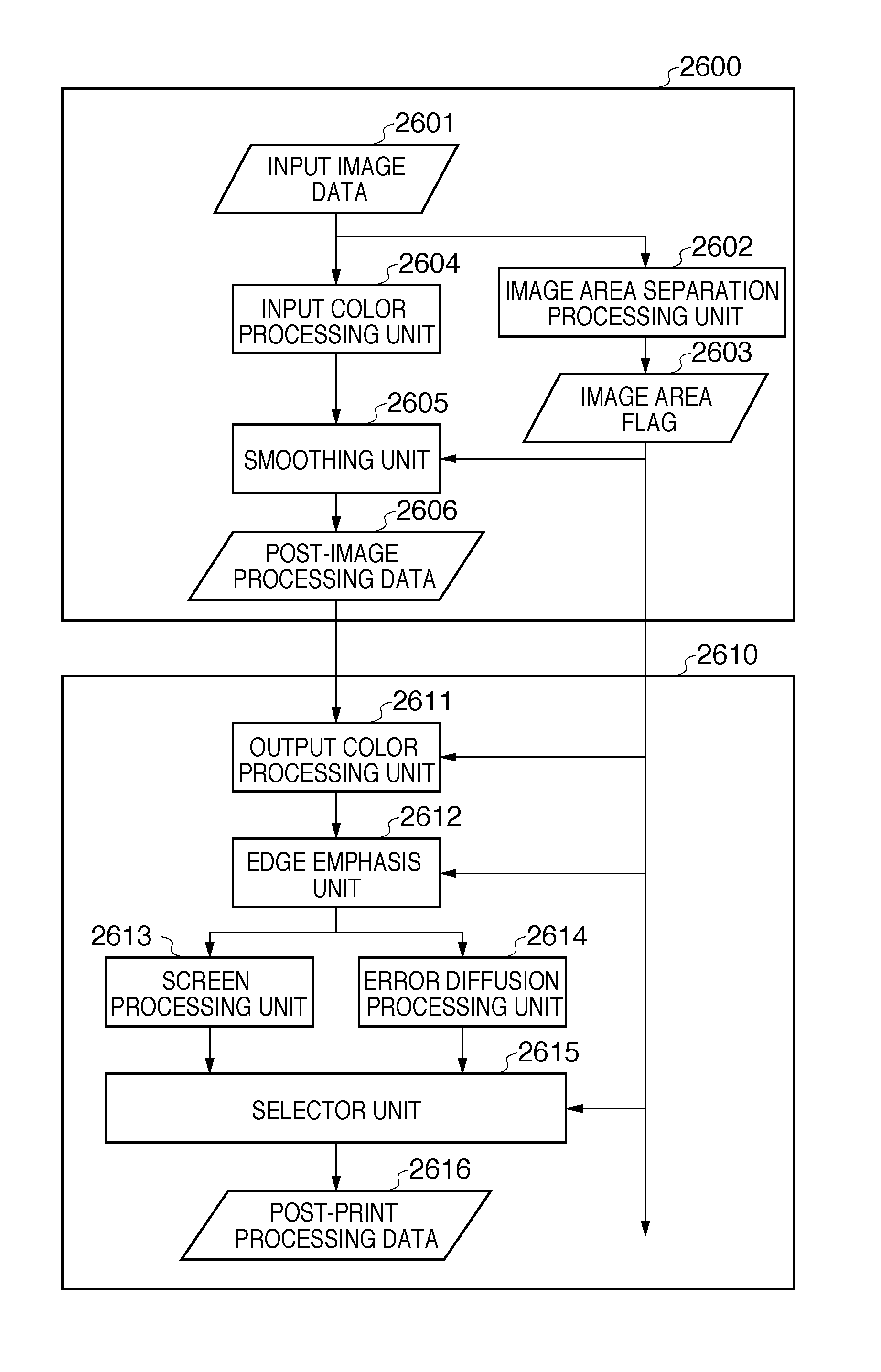
[0146]Embodiment 1 describes an example in which the MTF correction unit 2904 performs smoothing if the image area flag generated by the image area separation processing unit 2902 indicates “character”. Embodiment 3 describes a method for determining whether to perform smoothing in accordance with an MTF characteristic of edges in an input image.

[0147]FIG. 13 is a diagram showing such a processing structure. The processing structure shown in FIG. 13 is substantially the same as in FIG. 7 that is described in Embodiment 1. There are two differences in the processing, namely that an MTF determination unit 3509 has been added, and an MTF correction unit 3504. The MTF correction unit 3504 has a function for variably switching the level of MTF correction based on a signal from the MTF determination unit 3509, and is a constituent element that replaces the MTF correction unit 2904 that switches smoothing and edge emphasis based on the image area flags generated by the image area separatio...


PUM


Abstract

Each object in input image data is separated into an area by an image area separation unit. An area determined to be a character area based on the image area separation processing is smoothened by an MTF correction unit. The resulting data is then binarized by a binarizing unit. The binarized data is split according to types of objects, and characters and line drawings are vectorized and stored in a storage unit. Alternatively, the characters and line drawings are printed out.

Description

BACKGROUND OF THE INVENTION[0001]1. Field of the Invention[0002]The present invention relates to an image processing apparatus and an image processing method, and in particular to an image processing apparatus and image processing method that can restore image data that is more faithful to an original image, from image data on which another image processing apparatus has performed image processing.[0003]2. Description of the Related Art[0004]Digital multifunction peripherals (MFP) have conventionally been used in a standalone situation for copying use, but in recent years, as intranets and the Internet have become widely used, it has become possible to use MFPs via a network. An MFP connected to a network can, for example, receive image data that has been digitized by another MFP via the network, and print and file the received image data.[0005]There are cases in which various types of image processing are performed in MFPs in order to improve the quality of image data obtained by r...

Claims


Application Information

Patent Timeline
Patent Type & Authority Patents(United States)
IPC IPC(8): H04N1/409G06K9/46G06K15/00G06K9/18G06V30/224
CPCH04N1/40062H04N1/403H04N1/4092
Inventor SAKAUE, TSUTOMUNAMIKATA, TAKESHISANO, SHINJIARAKAWA, JUNYA
Owner CANON KK
Why Eureka
Try Eureka