Shielding case frame

a shielding case and frame technology, applied in the field of shielding cases, can solve the problems of high mold cost, low production efficiency, high design and machining requirements, etc., and achieve the effects of convenient machining, rapid and convenient removal of suction structure, and simple structur

Active Publication Date: 2019-04-30
SHENZHEN SUNWAY COMM
View PDF19 Cites 0 Cited by
  • Summary
  • Abstract
  • Description
  • Claims
  • Application Information

AI Technical Summary

Benefits of technology

[0016]The invention has the beneficial effects that the suction structure can be removed rapidly and conveniently by pressing the pressing parts with fingers without a special tool; the structure is simple, machining is convenient, and the production cost is low; the suction structure can be used for supporting the main body of the shielding case frame before being dismantled, so that the overall strength of the shielding case frame is improved, and the shielding case frame is not prone to deformation.

Problems solved by technology

The three designs all have respective limitation, as for the first design, a shearing tool is needed for shearing one by one after SMT, the production efficiency is low, and sufficient spaces need to be reserved at the shearing positions to prevent interference between the tool and the parts below and damage the parts during shearing.
As for the second design, since the structures have already been cut off from the molds, the design and machining requirements for the molds are high, and the mold cost is high.
The third design is only suitable for shielding cases with small sizes, and if the size of the frame is large, the frame can be poor in strength and is prone to deformation before SMT.

Method used


Image

  • Shielding case frame
  • Shielding case frame
  • Shielding case frame

Examples


first embodiment

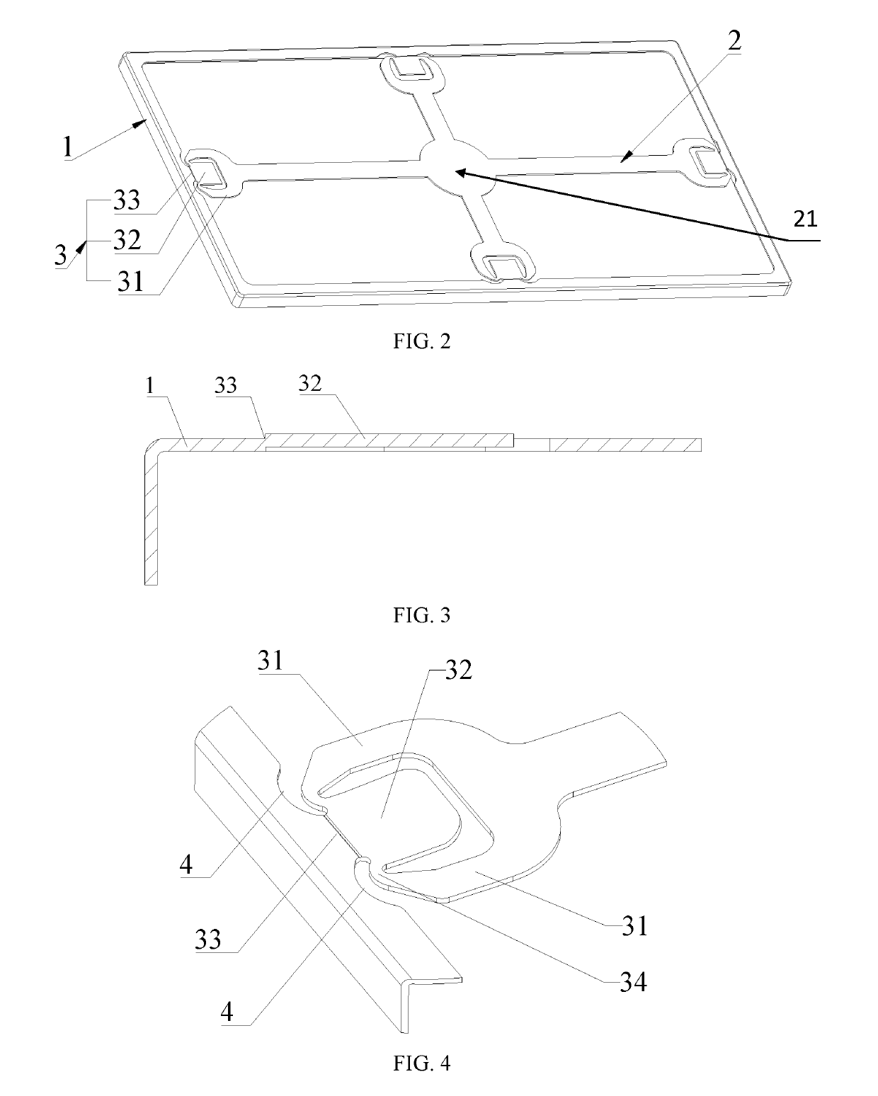
[0059]Please see FIGS. 2-5 for the first embodiment of the utility mode, as is shown in FIG. 2, a shielding case frame comprises a frame main body 1 and a suction structure 2, wherein the suction structure 2 is connected with the frame main body 1 through at least one precut structure 3; the precut structure 3 comprises extension parts 31 arranged on the suction structure 2, a pressing part 32 connected with the extension parts 31, and a precut part 33; the pressing part 32 is connected with the frame main body 1 through the precut part 33, and the bottom surface or / and the top surface of the precut part 33 is provided with a precut groove. As is shown in FIG. 3, the precut part 33 can also not be provided with the precut groove, the precut part 33 can be set to be in a step shape, namely the longitudinal section of the precut part is in a step shape, and both the step and the precut groove can achieve the precut effect. Please see FIG. 2, in the embodiment, the suction structure 2 ...

second embodiment

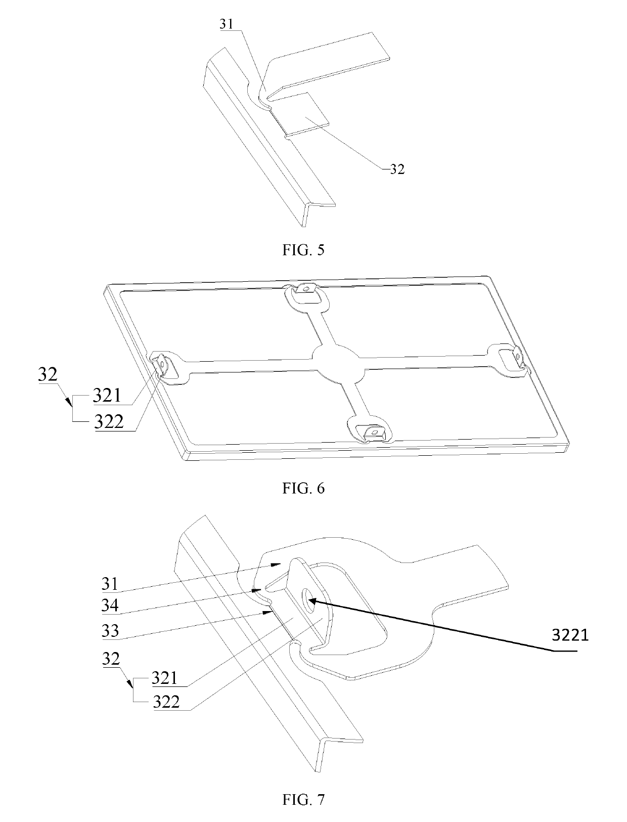
[0063]Please see FIG. 6 and FIG. 7, the second embodiment of the invention refers to the improvement of the pressing part based on the first embodiment and is different from the first embodiment in that the pressing part 32 is not a flat plate and comprises a first pressing part body 321 and a second pressing part body 322, wherein the first pressing part body 321 is connected with the precut part 33, the second pressing part body 322 is connected with the first pressing part body 321, an included angle is formed between the first pressing part body 321 and the second pressing part body 322, and the included angle is a right angle or an acute angle or an obtuse angle. The extension parts 31 are connected with the first pressing part body 321. By dividing the pressing part 32 into two non-coplanar parts, the suction structure 2 can be removed more easily and conveniently, and the production efficiency can be further improved.

[0064]For optimization, a through hole 3221 is set in the s...


PUM


Abstract

A shielding case frame has a frame main body and a suction structure. The suction structure is connected with the frame main body through at least one precut structure. The precut structure has extension parts arranged on the suction structure, a pressing part connected with the extension parts and a precut part. The pressing part is connected with the frame main body through the precut part. A bottom surface or / and a top surface of the precut part is provided with a precut groove.

Description

TECHNICAL FIELD[0001]The invention relates to shielding cases, in particular to a shielding case frame.DESCRIPTION OF RELATED ART[0002]For protecting electronic products against electromagnetic interference, all parts need to be shielded from interference through shielding cases. For conveniently repairing internal parts in the shielding cases, common shielding cases on the market are of a two-piece structure which having a frame and a cover. Since the shielding case frames need to be mounted on circuit boards through the surface mount technology (SMT), suction cups and adjoining structures of suction cups and frame need to be mounted on the frames.[0003]However, in order to reduce the weight of products and facilitate subsequent repairing, the suction cups and the adjoining structures on the shielding case frames need to be removed after SMT. In the prior art, three common designs for conveniently removing the suction cups and the adjoining structures are provided; according to the...

Claims


Application Information

Patent Timeline
Patent Type & Authority Patents(United States)
IPC IPC(8): H05K9/00H05K1/18
CPCH05K9/0032H05K2201/10424H05K2201/10371H05K1/181
Inventor CHEN, GAN
Owner SHENZHEN SUNWAY COMM
Why Eureka
Try Eureka