Automated self-loading cargo carrier for vehicles

a cargo carrier and vehicle technology, applied in the direction of loading/unloading vehicles, transportation items, vehicles with loading gates, etc., can solve the problems of not being able to address the problems common to these known devices, where to attach such devices, and prior art devices still require users to lift their cargo, so as to facilitate the storage of a variety of items

Active Publication Date: 2019-05-14
CARBONE FRANK LOUIS +1
View PDF47 Cites 16 Cited by
  • Summary
  • Abstract
  • Description
  • Claims
  • Application Information

AI Technical Summary

Benefits of technology

[0014]To minimize the limitations in the prior art, and to minimize other limitations that will be apparent upon reading and understanding the present specification, the present invention describes an automated self-loading cargo carrier for automobiles that facilitates storing a variety of items.

Problems solved by technology

Moreover, the prior art is riddled with distinct types of cargo carrying means ranging from modular rack systems, to extendable racks and motorized elevators that can be attached to the rear, the roof or other parts of a vehicle.
Nevertheless, despite the variety of disclosed devices, the prior art falls short of addressing several problems common to these known devices.
For example, a common obstacle is where to attach such devices (often including container or platforms for containers) on a vehicle.
A persisting problem however, is that prior art devices still require a user to lift their cargo up to a platform, storage container, etc.
When coupled to the roof, such required lifting may prove prohibitive to most users due to height and strength limitations; multiple users may be required for heavier loads or users may be limited in what items they may store with such devices (i.e. limited by the weight a user may be able to lift rather than the weight capacity of the device itself).
As such, many prior art devices are not used to their fullest potential due to this limitation.
Although the mounts can include a fluid suspension, lifting the cargo up into the container must be done manually, which as mentioned above significantly limits the type and weight limit of the cargo that a user will be able to load using this device.
Again, lifting the cargo up to the horizontal position can be difficult for most potential consumers, and as mentioned above significantly limits the type and weight limit of the cargo that a user will be able to load using this device.
Although this device appears to implement a motor for lifting the device between the loading position and the transport position, its use appears cumbersome and in order to facilitate the movement of the device, storage space must be substantially limited.
Limited cargo space is yet another problem that has not been adequately addressed, especially by devices that implement motorized lifting mechanisms.
Each of these devices fails to disclose an adequate storage space; likely due to their cumbersome lifting mechanisms that lake up space otherwise suitable for cargo.
As such, although the cargo space is increased, the implementation of clamshell compartments introduces still other setbacks.
Because of their narrow shape, most consumers install them on one side of their vehicle's roof—otherwise they are unreachable.
This creates an unstable load while driving and is therefore undesirable.
Newer model clamshells open and lock from either of their longitudinal sides, but the hinging and locking mechanisms, and the cargo containers themselves, are flimsy; consequently, the hinges and locks are prone to breaking, which is a common complaint amongst current clamshell owners.
Current devices available on the market are also of limited volume, typically occupying less than 50% of the vehicle roof's area, provoking some users to mount two devices side by side in order to accommodate all of their luggage and equipment.
But the most limiting factor of such existing devices is that they are very difficult to load and access, typically requiring a step ladder or other specialized ladders (e.g. one that fits over the rear tire) in order to reach the device once it is mounted on top of the vehicle.
Therefore, there exists a previously unappreciated need, and an inadequately addressed problem, requiring a new and improved cargo carrier for vehicles.

Method used


Image

  • Automated self-loading cargo carrier for vehicles
  • Automated self-loading cargo carrier for vehicles
  • Automated self-loading cargo carrier for vehicles

Examples


Embodiment Construction

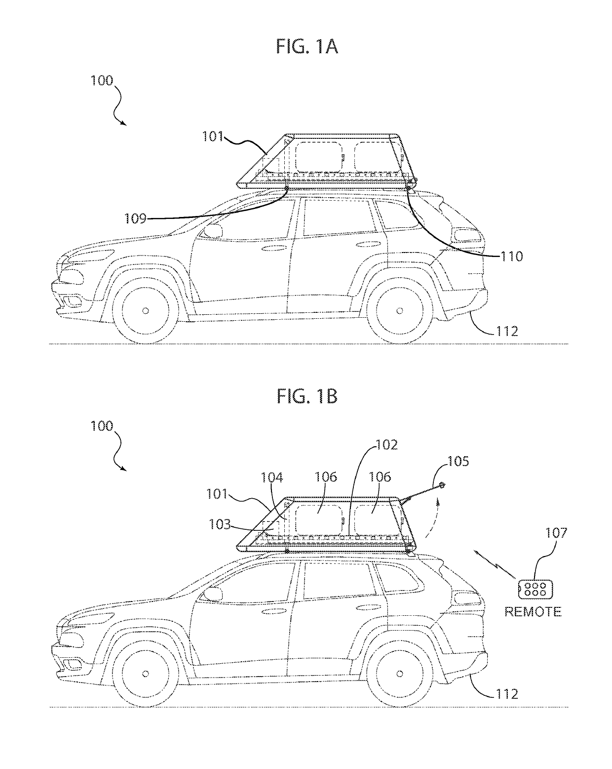
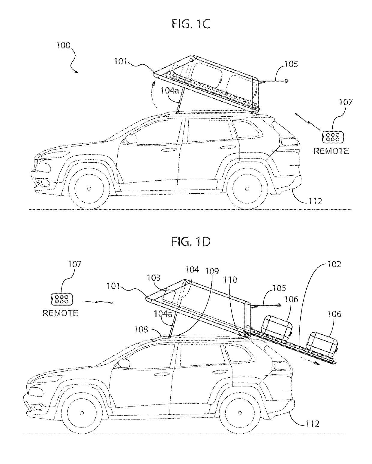
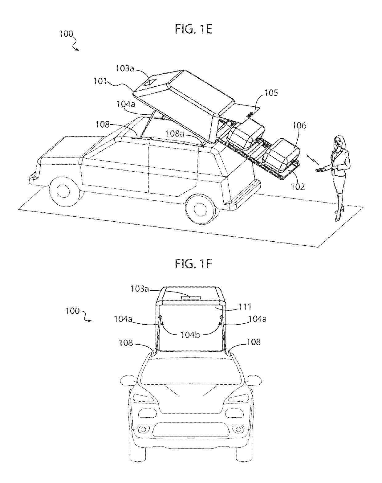
[0049]In the following discussion that addresses a number of embodiments and applications of the present invention, reference is made to the accompanying drawings that form a part thereof, where depictions are made, by way of illustration, of specific embodiments in which the invention may be practiced. It is to be understood that other embodiments may be utilized, and changes may be made without departing from the scope of the invention. Wherever possible, the same reference numbers are used in the drawings and the following description to refer to the same or similar elements.

[0050]In the following detailed description, numerous specific details are set forth by way of examples in order to provide a thorough understanding of the relevant teachings. However, it should be apparent to those skilled in the art that the present teachings may be practiced without such details. In other instances, well known structures, components and / or functional or structural relationship thereof, etc...


PUM


Abstract

The invention involves a cargo carrier for vehicles that facilitates loading and unloading of items onto an enclosure; the cargo carrier may be automated and self-loading via actuators and a motorized mechanism that may be remotely controlled. The actuators may be configured to tilt the enclosure and one or more motors may be configured to deploy a deployable tray housed within the enclosure, which minimizes user loading or unloading labor. Typically, on a front end of the enclosure, one or more actuators may couple the enclosure to a front portion of a vehicle support structure. On a rear end of the enclosure, one or more rear fittings may be configured to tiltably couple the enclosure to a rear portion of the vehicle support structure. The deployable tray may include a conveyor mechanism to further facilitate loading or unloading.

Description

TECHNICAL FIELD OF THE INVENTION[0001]The present invention relates generally to a cargo carrier for vehicles. More specifically, the present invention relates to an automated self-loading cargo carrier for vehicles that facilitates loading and unloading of items onto an enclosure, via actuators and a motorized mechanism that may be remotely controlled.COPYRIGHT AND TRADEMARK NOTICE[0002]A portion of the disclosure of this patent application may contain material that is subject to copyright protection. The owner has no objection to the facsimile reproduction by anyone of the patent document or the patent disclosure, as it appears in the Patent and Trademark Office patent file or records, but otherwise reserves all copyrights whatsoever.[0003]Certain marks referenced herein may be common law or registered trademarks of third parties affiliated or unaffiliated with the applicant or the assignee. Use of these marks is by way of example and should not be construed as descriptive or to l...

Claims


Application Information

Patent Timeline
Patent Type & Authority Patents(United States)
IPC IPC(8): B60R9/042G05D3/10B60R9/055
CPCB60R9/042G05D3/10B60R9/055B60P1/30B60P1/003B60P1/433
Inventor CARBONE, FRANK LOUISCARBONE, DOMINIQUE ANNALISE
Owner CARBONE FRANK LOUIS
Why Eureka
Try Eureka