Washer and differential device

a technology of differential gears and washers, which is applied in the direction of differential gears, belts/chains/gearrings, and differential gears, can solve the problems of displaced pinion gear back face parts of washers covering the back face of pinion gears (differential gears), and cannot fully receive the load of side gears, so as to achieve the effect of effectively preventing the displacement of pinion gear back face parts

Inactive Publication Date: 2019-05-14
MUSA PRECISION IND CO LTD
View PDF11 Cites 2 Cited by
  • Summary
  • Abstract
  • Description
  • Claims
  • Application Information

AI Technical Summary

Benefits of technology

[0006]It is an object of the present invention to provide a washer that can suppress effectively displacement of a pinion gear back face part (differential gear back face part) of a washer due to rotational power in a rotational direction of a side gear, and to provide a differential device equipped with the washer.
[0009]In accordance with the present invention, it is possible to suppress displacement of the position of the differential gear back face part of the washer due to rotational power in the rotational direction of the output gear.

Problems solved by technology

Since a conventional washer has a small contact area with a side gear, there is a possibility that it will not be able to fully receive the load of the side gear.
However, with a combination of these techniques, there is a possibility that a pinion gear back face part of the washer covering a back face of the pinion gear (differential gear) will be displaced due to rotational power in a rotational direction (ring gear rotational direction) of the side gear (output gear).

Method used


Image

  • Washer and differential device
  • Washer and differential device
  • Washer and differential device

Examples


Embodiment Construction

[0018]Embodiments of the present invention are explained below by reference to the attached drawings.

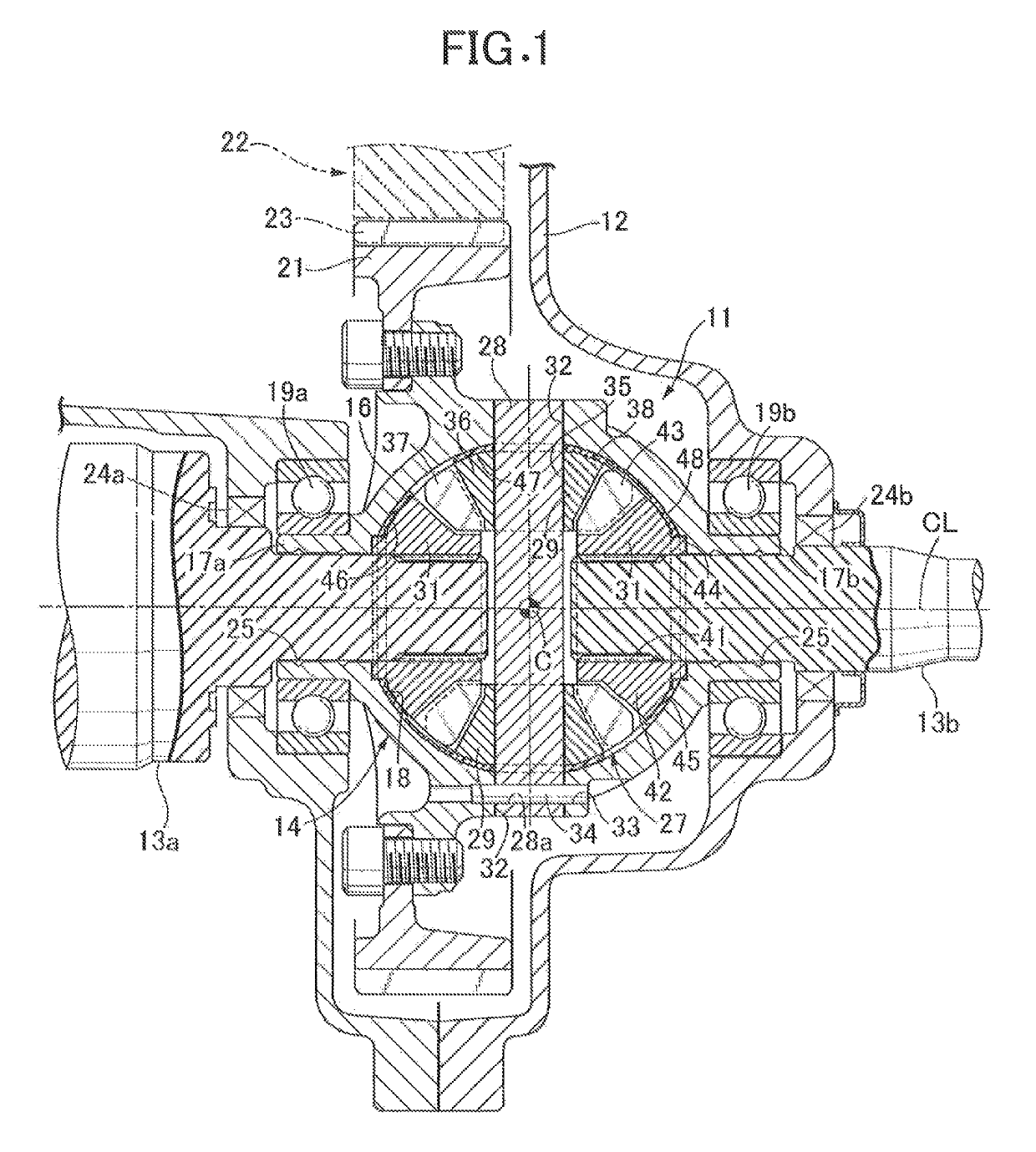
[0019]FIG. 1 schematically shows the overall arrangement of a differential device 11 related to one embodiment of the present invention. An automobile includes a transmission case 12 that is disposed next to for example an engine (not illustrated) as a power source mounted on the automobile and houses a transmission (not illustrated) and the differential device 11. For example, a pair of left and right output shafts 13a and 13b connected to axles are supported on the transmission case 12 so as to be rotatable around a central axis CL. The two output shafts 13a and 13b are disposed coaxially to each other and each have one end joined to the differential device 11 within the transmission case 12.

[0020]The differential device 11 includes for example a differential case 14 supported on the transmission case 12 so as to be rotatable around the central axis CL, and a differential gear mech...


PUM


Abstract

A washer includes at least one differential gear back face part covering a back face of one differential gear, an output gear back face part covering a back face of one output gear, and at least one linking part connecting between the output gear back face part and the differential gear back face part, an abutment part being formed on an inner face of the differential gear back face part, the abutment part abutting against the back face of the differential gear via a flat face.

Description

BACKGROUND OF THE INVENTION[0001]Field of the Invention[0002]The present invention relates to a differential device that is mounted mainly on a vehicle and to a washer that can be used in a differential device, a transmission device and the like.[0003]Description of the Related Art[0004]In a differential device, a washer in which one pinion gear side and one side gear side are integrally formed has already been disclosed (e.g. Japanese Patent No. 5198970). Since a conventional washer has a small contact area with a side gear, there is a possibility that it will not be able to fully receive the load of the side gear. In order to solve this problem, a technique of covering the side gear side with a washer by using the technique of a washer having a spectacles shape, as disclosed in Japanese Patent No. 4857465, could be considered.[0005]However, with a combination of these techniques, there is a possibility that a pinion gear back face part of the washer covering a back face of the pin...

Claims


Application Information

Patent Timeline
Patent Type & Authority Patents(United States)
IPC IPC(8): F16H48/38F16H48/08
CPCF16H48/38F16H2048/387F16H48/08
Inventor MORI, HIROYUKI
Owner MUSA PRECISION IND CO LTD
Why Eureka
Try Eureka