Biological information detecting device

a biochemical information and detection device technology, applied in the field of biochemical information detection devices, can solve the problems of reducing the force of the electrode portions onto the biological surface, hindering the detection of an electrocardiographic signal, and difficulty in obtaining sufficient holding force with respect to the electrode portions, etc., to achieve stab detection, reduce cost, and simplify the structure

Active Publication Date: 2015-09-15
SEIKO INSTR INC
View PDF8 Cites 2 Cited by
  • Summary
  • Abstract
  • Description
  • Claims
  • Application Information

AI Technical Summary

Benefits of technology

[0012]According to the structure, as the guide portion allowing relative movement between each of the electrode portions and the fixing member in the extending direction and restricting movement in the width direction is provided, for example, when the fixing member is stretched / contracted along the extending direction due to deep breath or movement of the wearer, each of the electrode portions and the fixing member relatively move along the extending direction through the guide portion. That is, the electrode portions do not follow the stretch / contraction and so on of the fixing member, therefore, it is possible to restrain the electrode portions from being pulled in the extending direction with the stretch / contraction of the fixing member. Therefore, it is possible to suppress the displacement of positions of the electrode portions with respect to the wearer, which stabilize a contact state and contact positions of the electrode portions with respect to the wearer.
[0023]According to the present invention, a biological signal can be stably detected in good condition.

Problems solved by technology

However, in the case where the electrode portions are held by sandwiching the garment or the like by the hook in the above related art, it is difficult to obtain sufficient holding force with respect to the electrode portions only by sandwiching force of the hook.
Accordingly, there are problems that pressing force of the electrode portions onto the biological surface is reduced when the electrode portions are displaced or removed from the garment or the like due to a moving manner of a wearer, which may hinder good detection of an electrocardiographic signal.
Accordingly, there is a problem that contact positions of the electrode portions with respect to the biological surface are not stable, which hinders good detection of an electrocardiographic signal.
There is also a danger of disconnection and so on as the wires of the electrode portions are pulled along the extending direction of the attachment belt due to the stretching / contracting movement of the attachment belt.

Method used


Image

  • Biological information detecting device
  • Biological information detecting device
  • Biological information detecting device

Examples


first embodiment

[0034]Next, a first embodiment of the present invention will be explained with reference to the drawings.

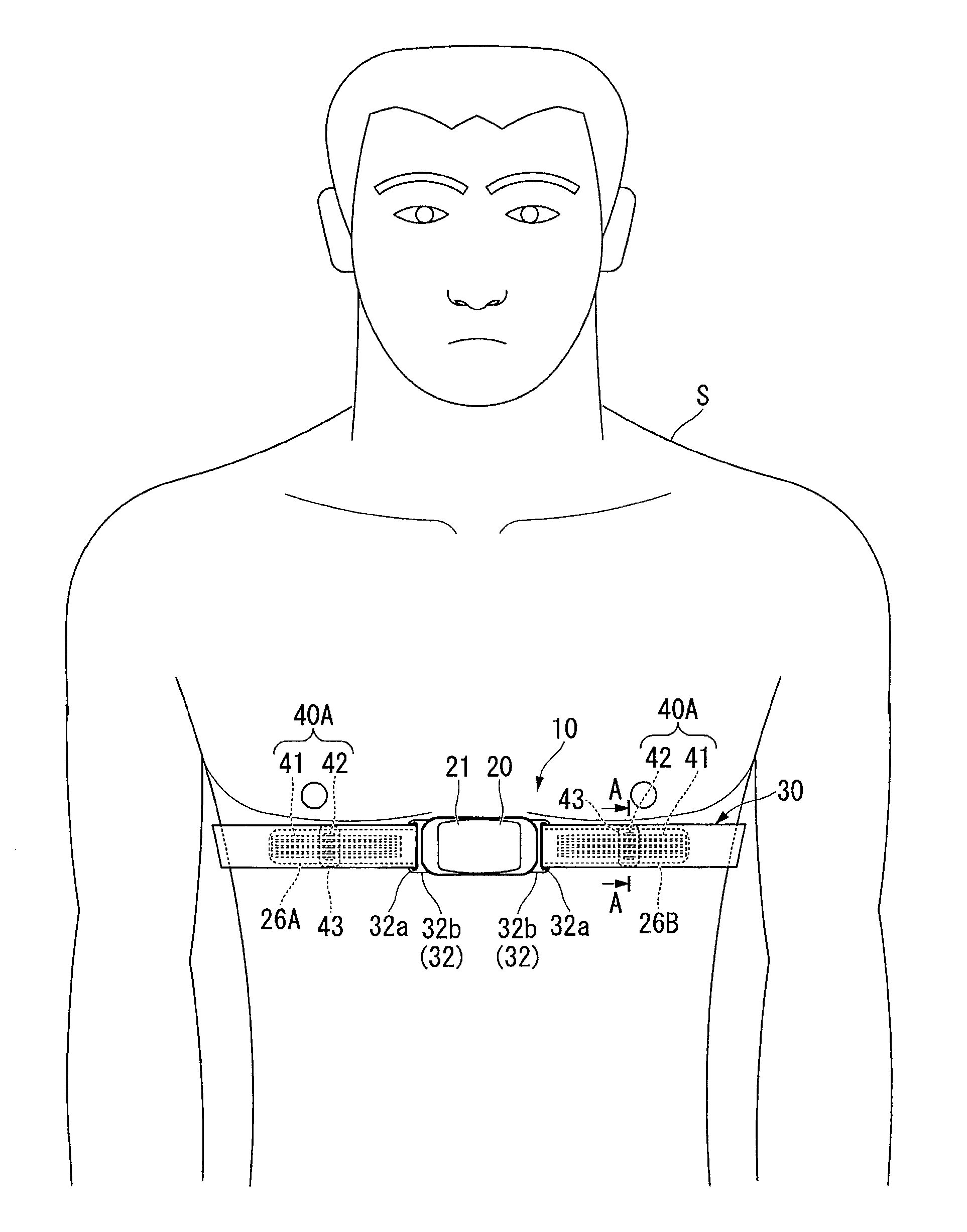
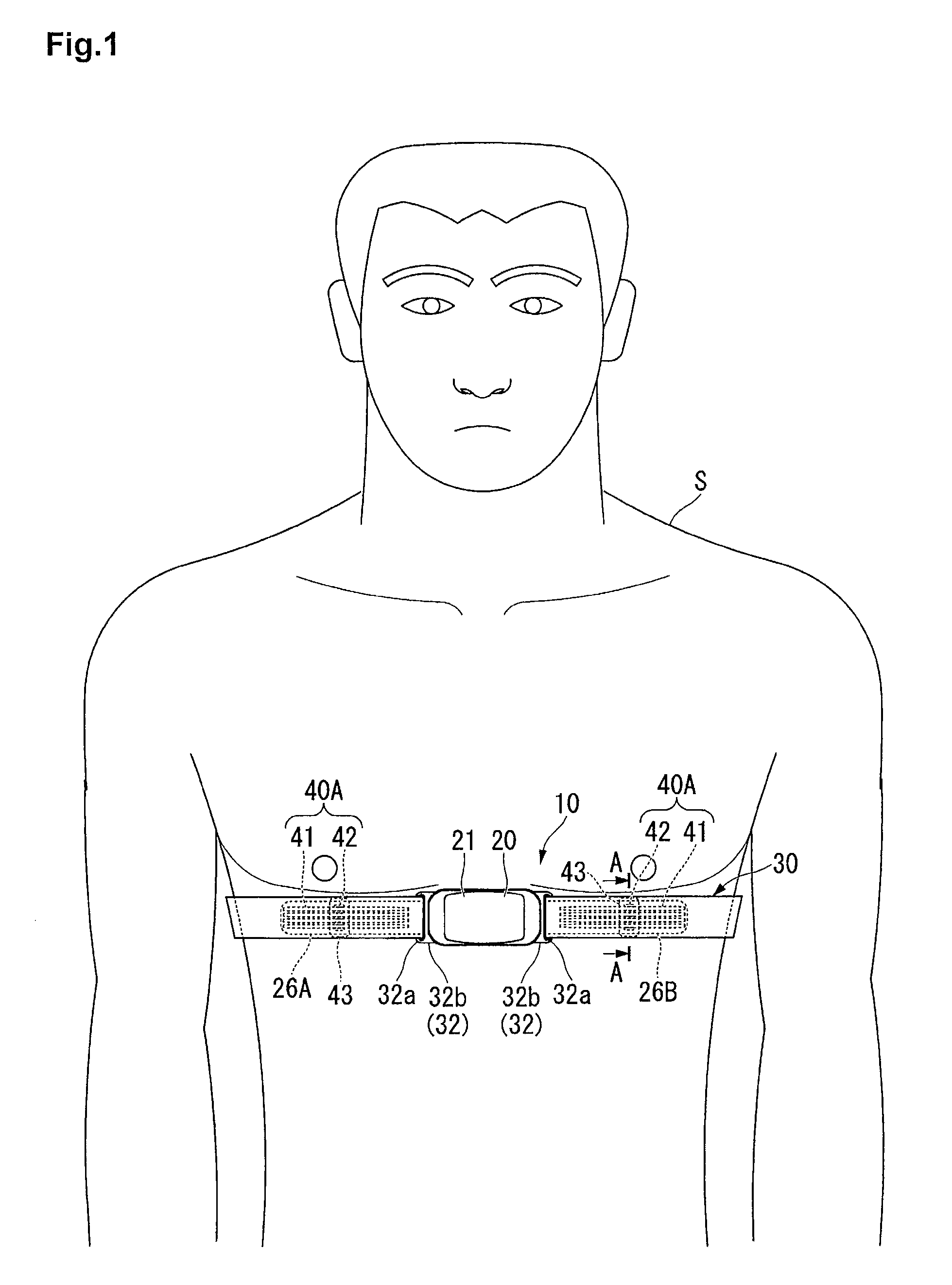
[0035]FIG. 1 is a front view showing a state where a heart rate measuring device 10 as a biological information detecting device according to the first embodiment of the present invention is attached to a wearer S.

[0036]As shown in FIG. 1, the heart rate measuring device (biological information detecting device) 10 detects an electrocardiographic signal generated by heartbeats by being attached to a chest as a biological surface of the wearer S and transmits the detected electrocardiographic signal by wireless communication.

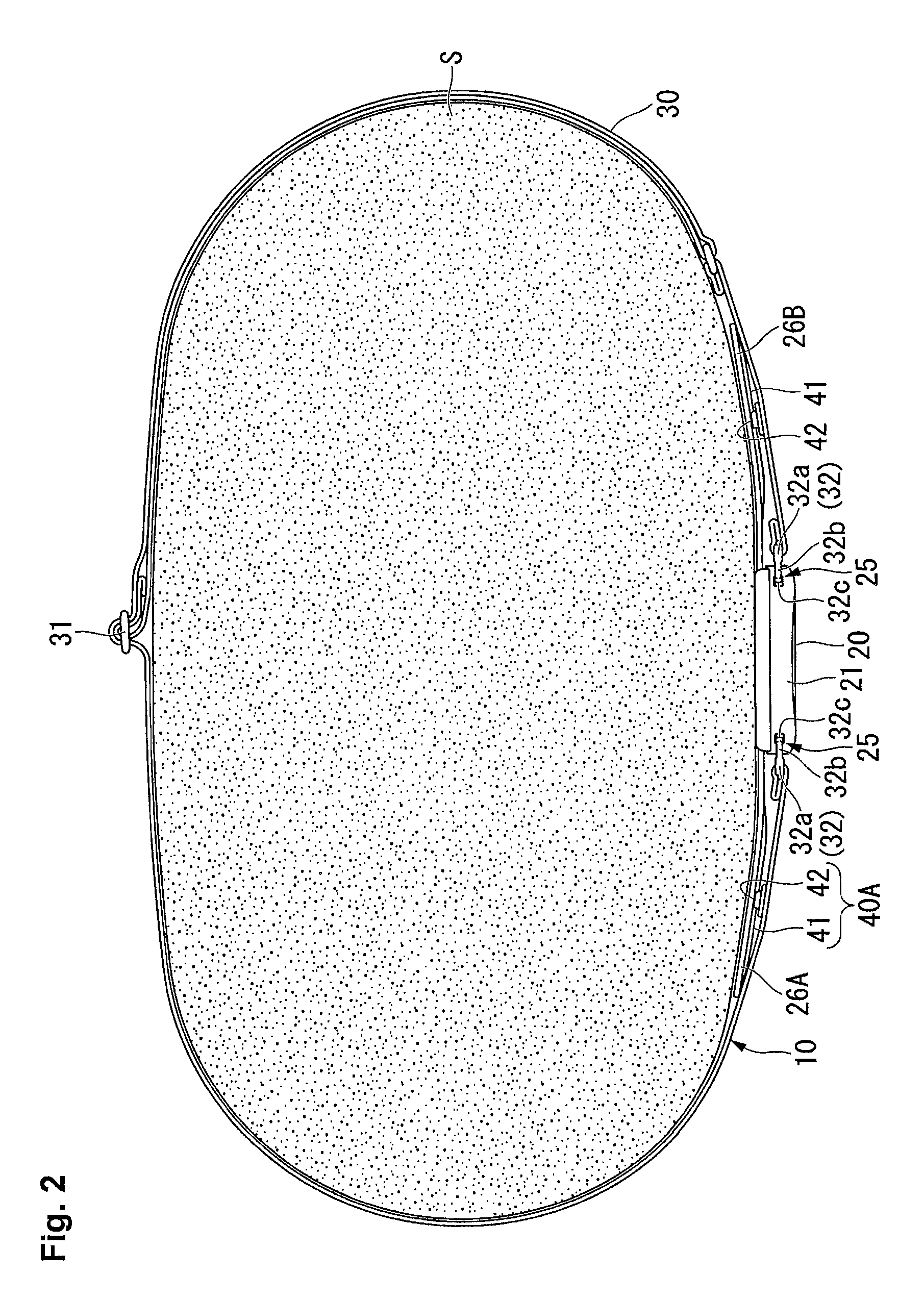
[0037]FIG. 2 is a transverse sectional view showing a state where the heart rate measuring device 10 is attached to the wearer S. FIG. 3 is an enlarged view of a relevant part of FIG. 2. FIG. 4 is an exploded perspective view showing the heart rate measuring device 10.

[0038]As shown in FIG. 1 to FIG. 4, the heart rate measuring device 10 includes a device body...

modification example of first embodiment

[0072]Next, a modification example of the above first embodiment will be shown. In the first embodiment, the case where the convex portions 42 in the fixing band 30 side have the rail shape extending along the extending direction has been explained, however, the present invention is not limited to this. For example, convex portions (engaged portions) 44 may have a cylindrical shape extending toward the electrode portions 26A / 26B side (the normal line direction of the surface 30f of the fixing band 30) as a guide portion 40B shown in FIG. 7.

[0073]According to the structure, the same operation and effect as the first embodiment can be obtained as well as the contact area between the protruding ridges 41 and the convex portions 44 along the extending direction can be reduced to be smaller than the rail-shaped convex portions 42 as in the first embodiment at the time of fitting the protruding ridges 41 to the convex portions 44. Accordingly, the fitting force between the protruding ridg...

second embodiment

[0081]Next, a second embodiment of the heart rate measuring device 10 according to the present invention will be explained. In the following explanation, the same components as the first embodiment are denoted by the same numerals and signs and explanation thereof is omitted. FIG. 10 is a view showing a structure of a guide portion 40E according to a second embodiment of the present invention. The present embodiment differs from the first embodiment in a point that edge portions in the width direction of each of the electrode portions (the other member) 26A and 26B are used as the guide portion 40E as shown in FIG. 10.

[0082]Specifically, the guide portion 40E according to the embodiment includes a pair of convex portions (engaging portions) 52 in the fixing band (fixing member, one member) 30, which protrude toward the electrode portions 26A / 26B. These convex portions 52 have a rail shape continuously extending along the extending direction. A width W1 between respective convex port...


PUM


Abstract

Provision of a biological information detecting device capable of stably detecting a biological signal in good condition. A device body, a pair of electrode portions 26A and 26B provided in the device body and respectively contacting a biological surface and a band-shaped fixing band 30 for covering the pair of electrode portions 26A and 26B and fixing the device body to a body are provided, and a guide portion 40A which allows relative movement between each of the electrode portions 26A / 26B and the fixing band 30 in an extending direction of the fixing band 30 and restricts movement in a width direction orthogonal to the extending direction is arranged between each of the electrode portions 26A / 26B and the fixing band 30.

Description

RELATED APPLICATIONS[0001]This application claims priority under 35 U.S.C. §119 to Japanese Patent Application No. 2013-222228 filed on Oct. 25, 2013, the entire content of which is hereby incorporated by reference.BACKGROUND OF THE INVENTION[0002]1. Field of the Invention[0003]The present invention relates to a biological information detecting device.[0004]2. Description of the Related Art[0005]There exist biological information detecting devices detecting a biological signal by allowing a sensor electrode to contact a biological surface. In this kind of biological information detecting devices, there is the one which measures a heart rate from the biological surface, for example, by detecting an electrocardiographic signal generated by heartbeats by the sensor electrode. As such biological information detecting device, there is the one including a pair of electrode portions and a device body transmitting an electrocardiographic signal detected by the electrode portions to the outs...

Claims


Application Information

Patent Timeline
Patent Type & Authority Patents(United States)
IPC IPC(8): A61B5/0408A61B5/00A61B5/024A61B5/04A61B5/332
CPCA61B5/6831A61B5/02438A61B5/04A61B5/0408A61B5/6823A61B5/24A61B5/25
Inventor KATO, TERUOOKUDA, HIDEKITERASAWA, DAIKANEKO, TAKAHIRO
Owner SEIKO INSTR INC
Why Eureka
Try Eureka