
Honeycomb filter

A filter, honeycomb technology, applied in filtration separation, dispersed particle filtration, machine/engine, etc., can solve the problems of exhaust gas leakage, filter performance reduction, exhaust gas purification efficiency reduction, etc., to achieve high heat resistance and strength. Effect

Active Publication Date: 2008-03-19
IBIDEN CO LTD
View PDF1 Cites 2 Cited by
  • Summary
  • Abstract
  • Description
  • Claims
  • Application Information

AI Technical Summary

Problems solved by technology

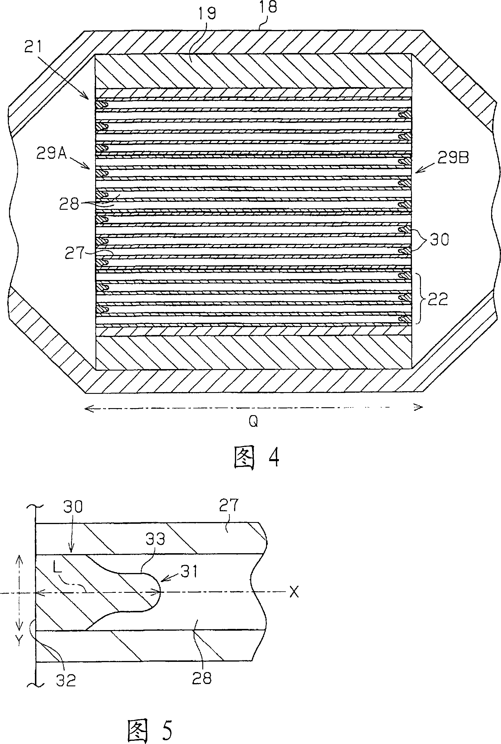
If a crack occurs in the sealing body, insufficiently purified exhaust gas will leak through the crack, resulting in a decrease in filter performance, that is, a decrease in the purification efficiency of exhaust gas.

Method used


Image

  • Honeycomb filter
  • Honeycomb filter
  • Honeycomb filter

Examples


Embodiment

[0090] Next, test examples and comparative examples of the present invention will be described.

[0091]

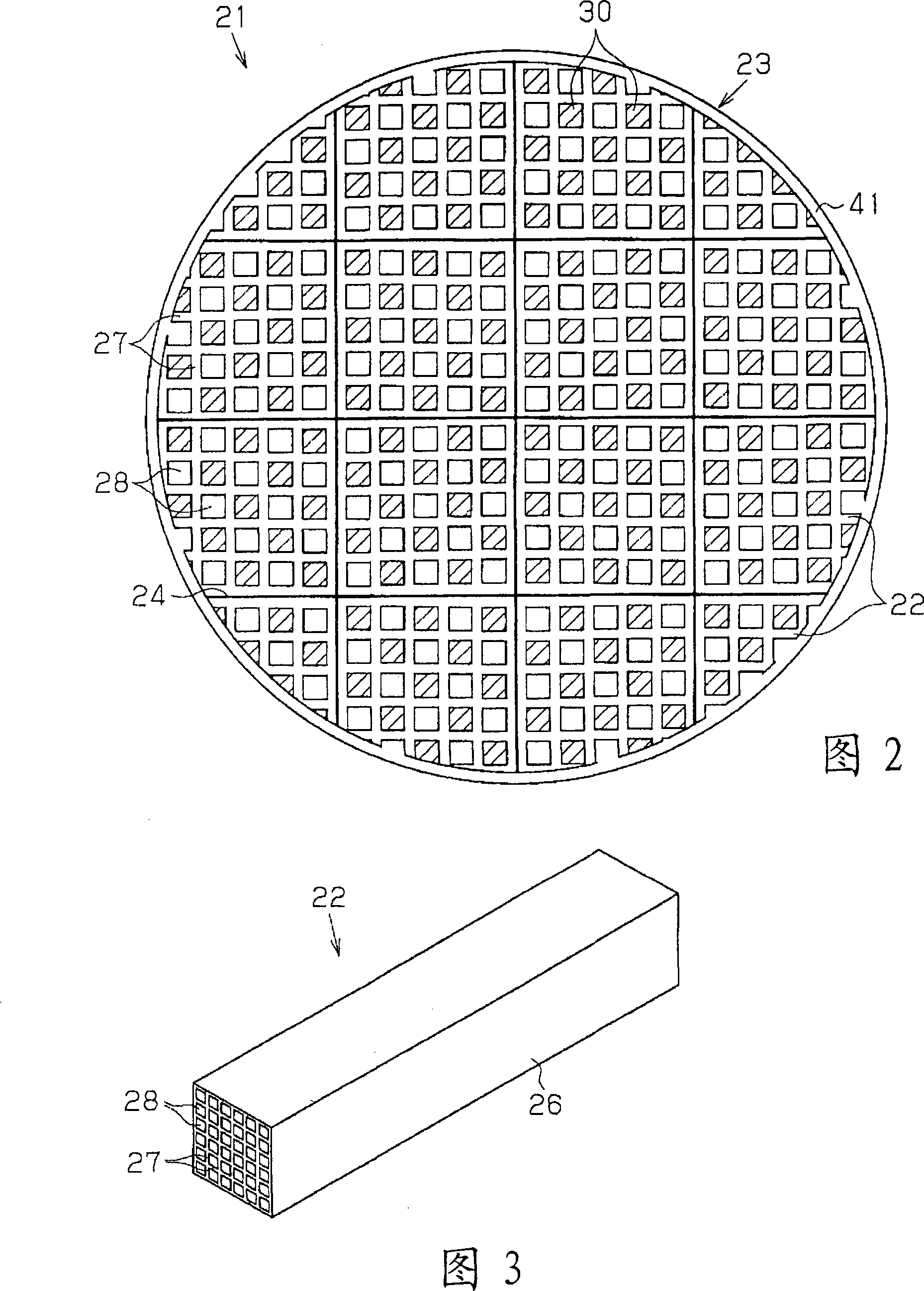
[0092] First, 7000 parts by weight of α-type silicon carbide powder with an average particle diameter of 10 μm and 3000 parts by weight of α-type silicon carbide powder with an average particle diameter of 0.5 μm were wet-mixed, and an organic binder (methyl 570 parts by weight of cellulose) and 1770 parts by weight of water were stirred to obtain a mixed composition. 330 parts by weight of a plasticizer (manufactured by NOF Corporation, Unilube (registered trademark)) and 150 parts by weight of a lubricant (glycerin) were added to this mixed composition, and after further stirring, extrusion molding was performed to obtain Prismatic preform shown in FIG. 3 .

[0093] Next, the preform is dried using a microwave dryer or the like to obtain a dried ceramic body. Fill the sealing body paste into the opening of the predetermined cell. After drying it with a dryer, degre...


PUM

PropertyMeasurementUnit
Thicknessaaaaaaaaaa
Diameteraaaaaaaaaa
Lengthaaaaaaaaaa

Abstract

Plugs (30) are formed of a material that has a greater total content of Al, Fe, B, Si, and free carbon than the material for a ho

Description

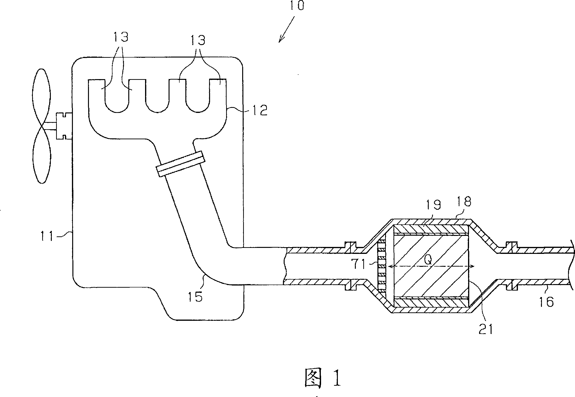
technical field [0001] The present invention relates to a honeycomb filter for trapping and removing particulate matter and the like contained in exhaust gas of, for example, internal combustion engines, boilers, and the like. Background technique [0002] In recent years, in consideration of the impact on the environment, the need to remove particulate matter contained in exhaust gas from combustion devices such as internal combustion engines and boilers has increased from exhaust gas. In particular, standards related to the removal of particulate matter (hereinafter referred to as PM) such as graphite particles discharged from diesel engines have been strengthened in Europe, America and Japan. As a trapping filter for removing PM and the like, a honeycomb structure called a DPF (Diesel Particulate Filter) is used. The honeycomb structure is accommodated in a casing provided in an exhaust passage of the combustion device. The honeycomb structure has a plurality of cells e...

Claims


Application Information

Patent Timeline
IPC IPC(8): B01D39/20B01D53/94B01D39/14B01J35/04B01D46/00F01N3/02B01D53/86F01N3/28
CPCB01D46/2474C04B2235/3418C04B2235/5445C04B2235/383C04B35/565C04B35/6365C04B2111/0081C04B2235/5228C04B37/005B01D46/2459C04B35/803C04B2235/721C04B2111/00793C04B2235/5224C04B35/806Y10S55/30C04B2235/526C04B2235/72Y10S55/05C04B35/478C04B38/0012F01N3/0222C04B2235/5264F01N3/035C04B2111/32F01N2330/06C04B2235/5436C04B2235/5472C04B2235/77B01D46/2466B01D53/944B01D2046/2496C04B35/6316F01N2330/30B01D46/2451C04B35/447Y10S55/10C04B35/6263C04B2237/083C04B35/195C04B2237/365Y10T428/24149C04B35/80B01D46/2498B01D46/2482B01D46/2476B01D46/2478C04B38/0054C04B38/0074B01D39/20B01D39/14B01D46/00B01D53/86
Inventor 早川修平
Owner IBIDEN CO LTD
Learn More