Tactical load-bearing vest

a load-bearing vest and tactical technology, applied in the field of load-bearing vests, can solve the problems of accelerating fatigue rate, heavy burden on the shoulders of users, and excessive load on users during sustained battles, and achieve the effect of convenient dislocation of the ves

Active Publication Date: 2019-05-14
KINNINGS BRADY ALAN ROBINSON
View PDF18 Cites 13 Cited by
  • Summary
  • Abstract
  • Description
  • Claims
  • Application Information

AI Technical Summary

Benefits of technology

[0004]The above-identified problems in the prior art may be overcome by providing an upper vest comprising a plurality of overlapping panels including a rigid back frame, a vertical spine extension, and a supporting waist belt comprising a cradle for receiving the spine extension. The spine extension may be raised when not in use, and lowered until it makes contact with the cradle of the supporting belt. In a lowered state, the spine extension ergonomically transfers load from the vest to the supporting belt. The cradle of the supporting belt may have a concave upper surface that is adapted to cradle the lowered spine extension. The spine extension may be automatically retracted into a raised state using a spring controlled by a trigger. A non-fixed coupling of the spine extension of the vest with the cradle of the supporting belt enables a user to easily dislocate the vest from the belt in order to perform a torso movement, such as a twist or a lean.
[0007]The chest panel couples at its top end to a front end of each shoulder panel and on either side to each waist panel. The chest panel may further include pockets or compartments for housing ballistic and Kevlar plates, and an attachment for a crotch protector. A height of the protective ballistic and / or Kevlar plates may be adjustable to protect differently-sized torsos. The chest panel further includes a quick-release mechanism for releasing the quick-release cable connecting the plurality of panels comprised by the vest, enabling the vest to fall apart quickly. For instance, a housing in the chest panel may be opened to expose the quick-release mechanism that is coupled to the quick-release cables routed through the other panels comprised by the vest.
[0008]Each shoulder panel may comprise an attachment point for enabling a backpack having compatible straps to be attached to the vest. The attachment point can include a buckle part coupled to the shoulder panel that is adapted to receive a corresponding buckle part coupled to a strap of the backpack, enabling a quick and removable attachment. When the vest is in use, a hard or stiff plastic curved portion within each shoulder panel transfers weight of the backpack from resting on the shoulders to resting on the supporting belt via the rigid back frame and spine extension. An upper surface of each shoulder panel may be concave in its cross-section, thereby forming a groove or channel for the shoulder straps of the backpack, and preventing the straps from slipping out. One or both shoulder panels may also comprise a rifle pad adapted for providing support to a stock of a rifle or a backpack strap when in use.

Problems solved by technology

It has become increasingly obvious to users and the U.S. Army that the additional technology users carry has put a heavy burden on their shoulders.
U.S. Army users, such as soldiers, carry excessive loads during sustained battles.
These loads are mainly distributed over their shoulders, limiting movement, speeding the rate of fatigue, and increasing the likelihood of numerous injuries.
Their loads far exceed the Army Chief of Staff's maximum weight limit, and they remain overburdened with the weight of technology.
However, existing plate carriers and “Interceptor” or IOTV style body armor are either too minimal to provide adequate safety, or too heavy to enable routine movements to be freely performed.

Method used


Image

  • Tactical load-bearing vest
  • Tactical load-bearing vest
  • Tactical load-bearing vest

Examples


Embodiment Construction

[0024]The following detailed description references specific embodiments of the subject disclosure and accompanying figures, including the respective best modes for carrying out each embodiment. It shall be understood that these illustrations are by way of example and not by way of limitation.

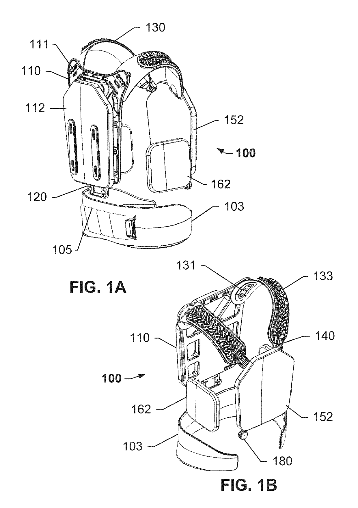
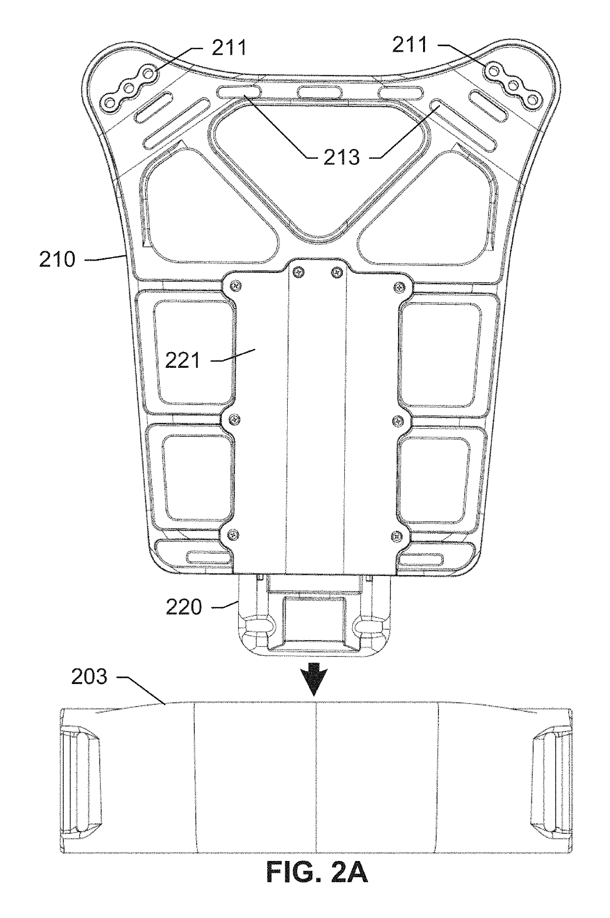
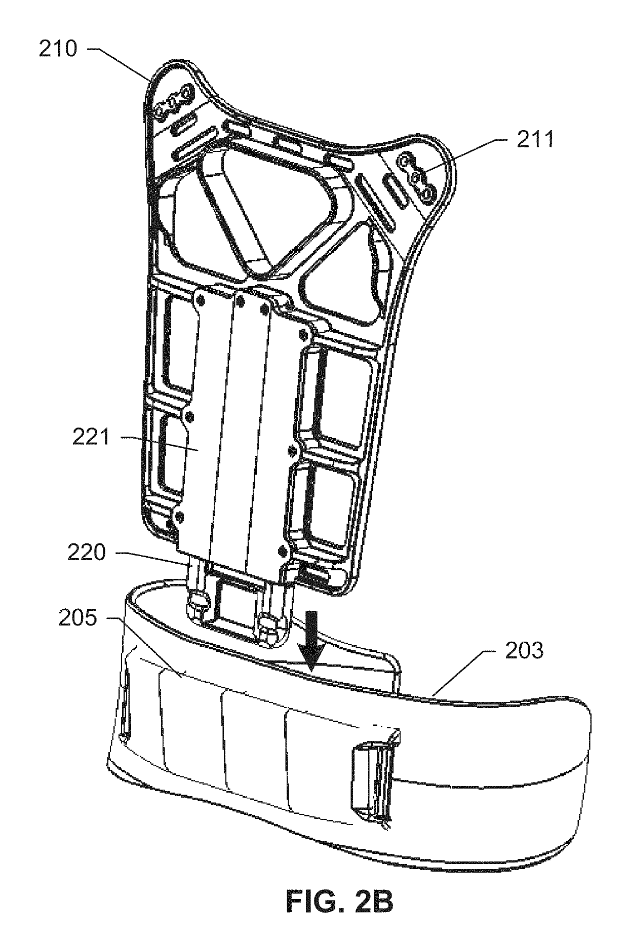
[0025]FIGS. 1A and 1B show views of an assembled vest 100 and a supporting waist belt 103, according to an exemplary embodiment of the subject disclosure. With reference to FIG. 1A, an upper vest 100 comprises a plurality of overlapping panels including a rigid back frame 110 coupled to a vertical spine extension 120, and a supporting waist belt 103 comprising a cradle 105 for receiving the vertical spine extension 120. Spine extension 120 may be raised or retracted when not in use, and lowered or extended until it makes contact with cradle 105 of supporting belt 103. In a lowered state, spine extension 120 ergonomically transfers load from the shoulder panels 130 to supporting belt 103 via the...


PUM


Abstract

This disclosure relates generally to a tactical load-bearing system comprising a vest and a supporting waist belt. A rigid rear frame comprising a spine extension, and a pair of shoulder panels, enables a load transfer from a user's shoulders to the supporting waist belt via the spine extension. A plurality of fabric panels including pockets for housing ballistic plates and attachment mechanisms for coupling together may also be quickly decoupled by a quick-release mechanism that comprises one or more quick-release cables. The rigid rear frame may include a rigging system or a rack system, enabling a user to carry additional equipment on the vest, such as a radio, battery, etc. A fine adjustment mechanism includes a tension cable routed through a pair of waist panels and coupled with a pair of tension plates located adjacent a back end of each waist panel. The modular coupling of each panel combined with the non-fixed load-bearing mechanism and quick-release mechanism enable users such as military personnel to respond to situations without being hindered by existing bulky or non-ergonomic load-carrying systems.

Description

[0001]This application claims priority to U.S. Provisional Patent Application Ser. No. 62 / 030,162, filed on Jul. 29, 2014, the contents which are hereby incorporated by reference herein in their entirety into this disclosure.TECHNICAL FIELD[0002]The subject disclosure relates generally to tactical body armor. Specifically, the subject disclosure relates to a load-bearing vest.BACKGROUND OF THE SUBJECT DISCLOSURE[0003]It has become increasingly obvious to users and the U.S. Army that the additional technology users carry has put a heavy burden on their shoulders. U.S. Army users, such as soldiers, carry excessive loads during sustained battles. These loads are mainly distributed over their shoulders, limiting movement, speeding the rate of fatigue, and increasing the likelihood of numerous injuries. These users have prolonged contact with the body armor, MOLLE and other combat equipment, spending days in a combat zone with only the equipment they carry. Their loads far exceed the Arm...

Claims


Application Information

Patent Timeline
Patent Type & Authority Patents(United States)
IPC IPC(8): F41H1/00A45F3/12A45F3/14A45F3/06F41H1/02A41D13/05A45F3/00
CPCF41H1/02A41D13/05A45F3/06A45F3/12A45F3/14A45F2003/146A45F2003/001A45F2003/003A45F2003/127
Inventor KINNINGS, BRADY ALAN ROBINSON
Owner KINNINGS BRADY ALAN ROBINSON
Why Eureka
Try Eureka