Medical electrode, electrode bundle and electrode bundle array

a technology of electrode bundles and electrode bundles, applied in the field of medical electrodes, can solve the problems of non-uniform or radiating movement around the arteries, reduce the quality of recordings/stimulations, injure the tissue, etc., and achieve the effect of easy dislocation

Active Publication Date: 2013-02-26
NEURONANO AB
View PDF12 Cites 18 Cited by
  • Summary
  • Abstract
  • Description
  • Claims
  • Application Information

AI Technical Summary

Benefits of technology

[0004]A first object of the invention is to provide an electrode of the aforementioned kind, which is adapted to move with the tissue into which it has been inserted or in which it has been implanted without being easily dislocated.

Problems solved by technology

For example, each heart beat causes a non-uniform or radiating movement around the arteries.
When a straight and non-elastic wire runs through an area that is not moving uniformly, the wire will tend to slide within the tissue, thus causing mechanical friction with and / or altered tension within the surrounding tissue, which in turn may injure the tissue.
Such movements will reduce the quality of recordings / stimulations that can be obtained with the electrode and may also cause a tissue reaction to the electrode.
Tissue movements affecting a wire electrode will be propagated to the anchoring means, resulting in the risk of injury to adjacent tissue.

Method used


Image

  • Medical electrode, electrode bundle and electrode bundle array
  • Medical electrode, electrode bundle and electrode bundle array
  • Medical electrode, electrode bundle and electrode bundle array

Examples


first embodiment

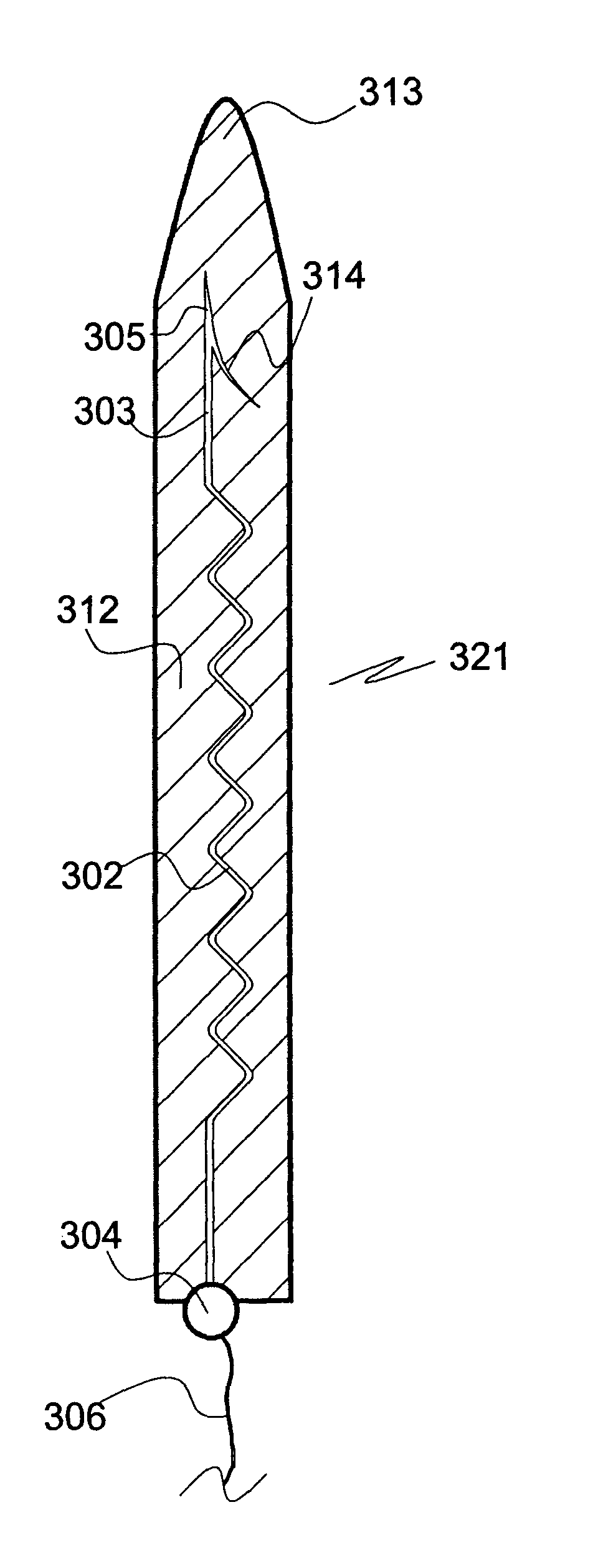
[0067]a matrix-embedded bundle 411 of four electrodes of the invention is shown in FIGS. 5a, 5b. The electrodes, which are of the kind of the electrode 101 of FIGS. 2a, 2b, are disposed in parallel and equidistantly from the rotational axis S of the bundle 411 in a dissolvable matrix body 412. In respect of the electrode body 402a of the first electrode, the bodies 402b, 402c, 402d of the other electrodes are disposed in an angle of 90°, 180° and 240°, respectively. In FIG. 5a the tip sections 403a, 403c and the bases 404a, 404c of the first and third electrodes, respectively, are also shown. The generally cylindrically tapering matrix body 412 tapers in a distal direction, only slightly at start but more pronounced towards its distal pointed end 413.

second embodiment

[0068]a matrix-embedded bundle 511 of four electrodes of the invention shown in FIG. 6 comprises four electrodes of the kind disclosed in FIGS. 2a, 2b and in the same disposition in respect of a rotational axis S′ as in the matrix-embedded electrode bundle 411 of FIGS. 5a, 5b. In contrast to the embodiment of FIGS. 5a, 5b the matrix body comprises two sections, a proximal section 512′ enclosing the electrode bodies 502a, 502c, etc., and a distal section 512″ enclosing their tip sections 503a, 503c. The dissolution rate of the proximal matrix body section 512′ is slower than that of the distal matrix body section 512″. This allows insertion of the entire matrix-embedded bundle 511 to a desired first depth or level of a soft tissue and, upon dissolution of the distal section 512″ material further insertion to a second depth or level, during which the now unsupported tips sections 503a etc. of the first electrode 502a, 503a, 504a and of the other electrodes are no longer immobilized bu...

third embodiment

[0071]the electrode bundle of the invention shown in FIG. 13 comprises four electrodes with extendible electrode bodies 802a, 802c attached to bases 804a, 804c. The bundle is embedded in a dissolvable matrix body 812 narrowing towards its distal tip 813. The electrode bases 804a, 804c are moulded in an electrode holder disk 807 from which their rear portions provided with conductors 806a, 806c extend. The electrode holder disk 807 is made of a non-conducting polymer material. This embodiment allows to keep the proximal portions of the electrodes at a desired distance, whereas their distal portions can move more freely.

[0072]A third embodiment of the electrode bundle array 920 of the invention is shown in FIG. 9. It differs from the electrode bundle array 620 of FIGS. 7a, 7b in that electrodes of the invention with tip sections 903a, 903c of different length and electrode bodies 902a, 902c of same length are comprised by a first electrode bundle embedded in a matrix 912a, and that a ...


PUM


Abstract

A medical microelectrode includes portions capable of movement relative to each other when implanted in or inserted into soft tissue, so as to increase or decrease their distance along the electrode. The electrode is at least partially embedded in a substantially rigid biocompatible matrix that is soluble or biodegradable a body fluid. Also disclosed are uses of the microelectrode; microelectrode bundles and arrays of microelectrode bundles and their uses; methods for inserting or implanting microelectrodes, microelectrode bundles and arrays of microelectrode bundles in soft tissue.

Description

CROSS REFERENCE TO RELATED APPLICATIONS[0001]The present application is a 35 U.S.C. §371 National Phase conversion of PCT / SE2008 / 000680, filed Dec. 3, 2008, which claims benefit of Swedish Application No. 0702740-2, filed Dec. 10, 2007, the disclosure of which is incorporated herein by reference. The PCT International Application was published in the English language.FIELD OF THE INVENTION[0002]The invention relates to a medical electrode, in particular a medical microelectrode, to a bundle of such electrodes, and to an array of such electrodes and / or electrode bundles. The medical electrode, the electrode bundle and the array of electrodes or electrode bundles of the invention are intended for insertion into soft tissue such as the brain, the spinal cord, endocrine organs, muscles, and connective tissue.BACKGROUND OF THE INVENTION[0003]Electrodes that can be implanted for a long time into the central nervous system (CNS) have a wide field of application. In principle, all brain nuc...

Claims


Application Information

Patent Timeline
Patent Type & Authority Patents(United States)
IPC IPC(8): A61B5/04A61N1/05
CPCA61N1/0551A61N1/0558A61N1/3605A61N1/375A61N1/37518
Inventor SCHOUENBORG, JENS
Owner NEURONANO AB
Why Eureka
Try Eureka