
Female side connector for high current

a technology of female side connector and high current, which is applied in the direction of coupling contact member, coupling device connection, securing/insulating coupling contact member, etc., can solve the problems of increasing manufacturing cost, increasing the length of the female side connector, so as to eliminate the insertion resistance, facilitate manufacturing, and simplify the effect of insertion of the card edg

Inactive Publication Date: 2007-01-30
YAMAICHI ELECTRONICS
View PDF16 Cites 20 Cited by
  • Summary
  • Abstract
  • Description
  • Claims
  • Application Information

AI Technical Summary

Benefits of technology

The present invention provides a female side connector for high current that can be easily connected to a male side connector, allow a high current to pass through it, and be manufactured at a lower cost. The female side connector includes a contact unit with a contact, a contact support section, and a connection terminal. The contact is made up of a plurality of thin plate-like contact elements with different positions of contact points. The contact points of the contact elements are dislocated, making it easy to insert a male side connector without deforming all the contact elements simultaneously. The female side connector also includes a driving arm or an operation lever that can open the contact points in a forced manner, simplifying the insertion process. The contact is formed by superposing thin plate-like contact elements in the plate thickness direction, making it easy to manufacture and a low cost. The two neighboring contacts are arranged symmetrically and in a zigzag manner, allowing for a compact connector design with a high number of contacts.

Problems solved by technology

For example, in the female side connector 1 disclosed in Patent Reference No. 2002-056910, considering the conductor resistance and the contact resistance as described above, the width, height, and length of the female side connector inevitably become larger and also the manufacture of the connector becomes more difficult, thus increasing the manufacturing cost.
As a result, the card edge is difficult to be engaged or disengaged, the card edge is damaged, and the pad part of the card edge may be broken in some cases.

Method used


Image

  • Female side connector for high current
  • Female side connector for high current
  • Female side connector for high current

Examples


embodiment 3

[0079]Next, with reference to FIG. 11 and FIGS. 12A, 12B, and 12C, Embodiment 3 according to the present invention will be described. FIG. 11 shows the sixth contact element. FIG. 12A is a schematic cross sectional view taken at the line XIIA—XIIA of the connector of FIG. 1 as in FIG. 3A in which a male side connector is not inserted. FIG. 12B is an enlarged cross-sectional view of the main part showing a process for inserting the male side connector. FIG. 12C is an enlarged cross-sectional view of the main part in which the male side connector is inserted.

[0080]The components in Embodiment 3 that correspond to those of Embodiment 1 are denoted such that the reference numerals showing such components of Embodiment 3 are added with 200.

[0081]Embodiment 3 is different somewhat from the above Embodiment 2. Specifically, in Embodiment 3, the sixth contact element 230A shown in FIG. 11 is alternatively superposed with the fifth contact element 230B, that has exactly the same structure as...


PUM


Abstract

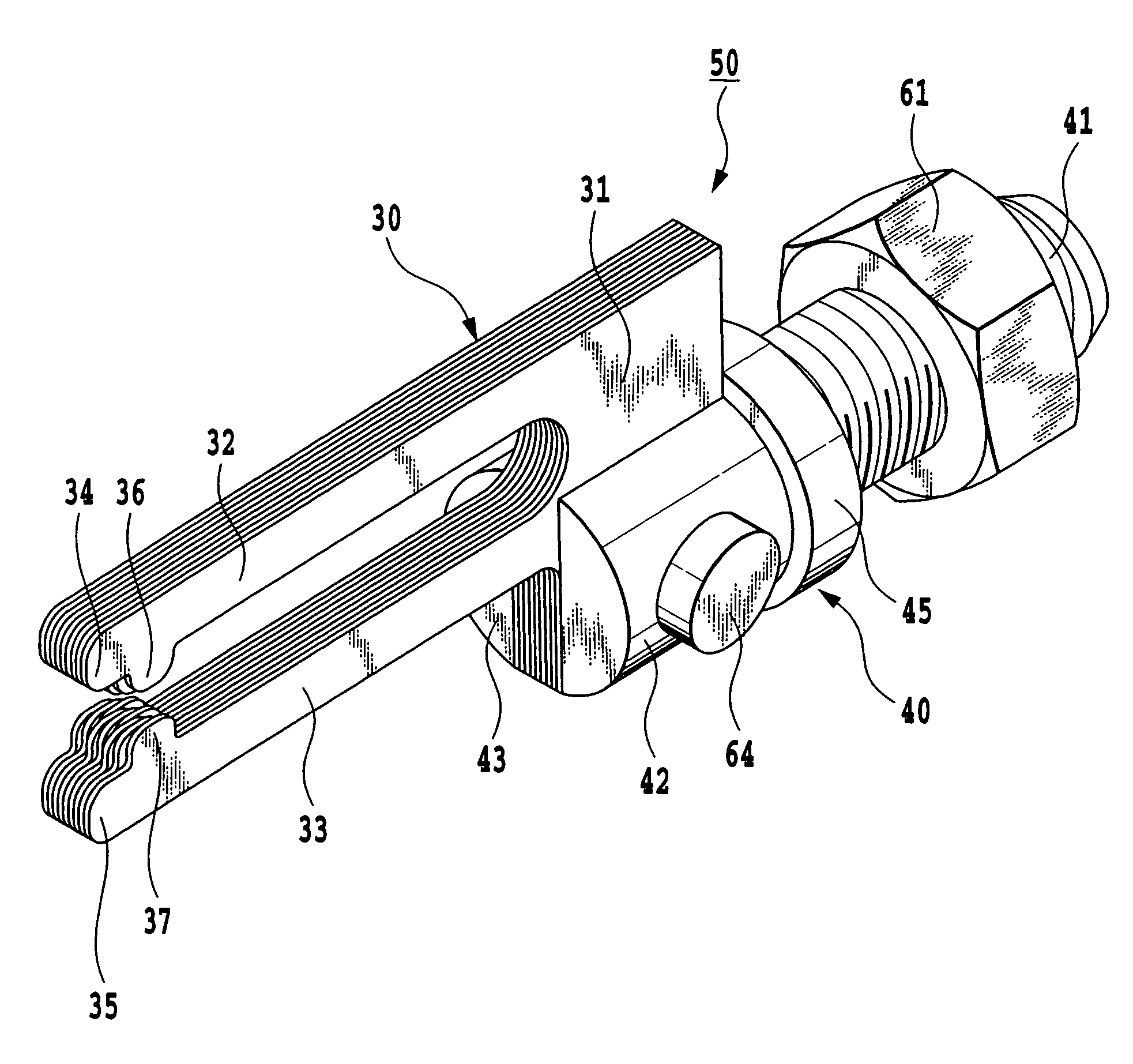
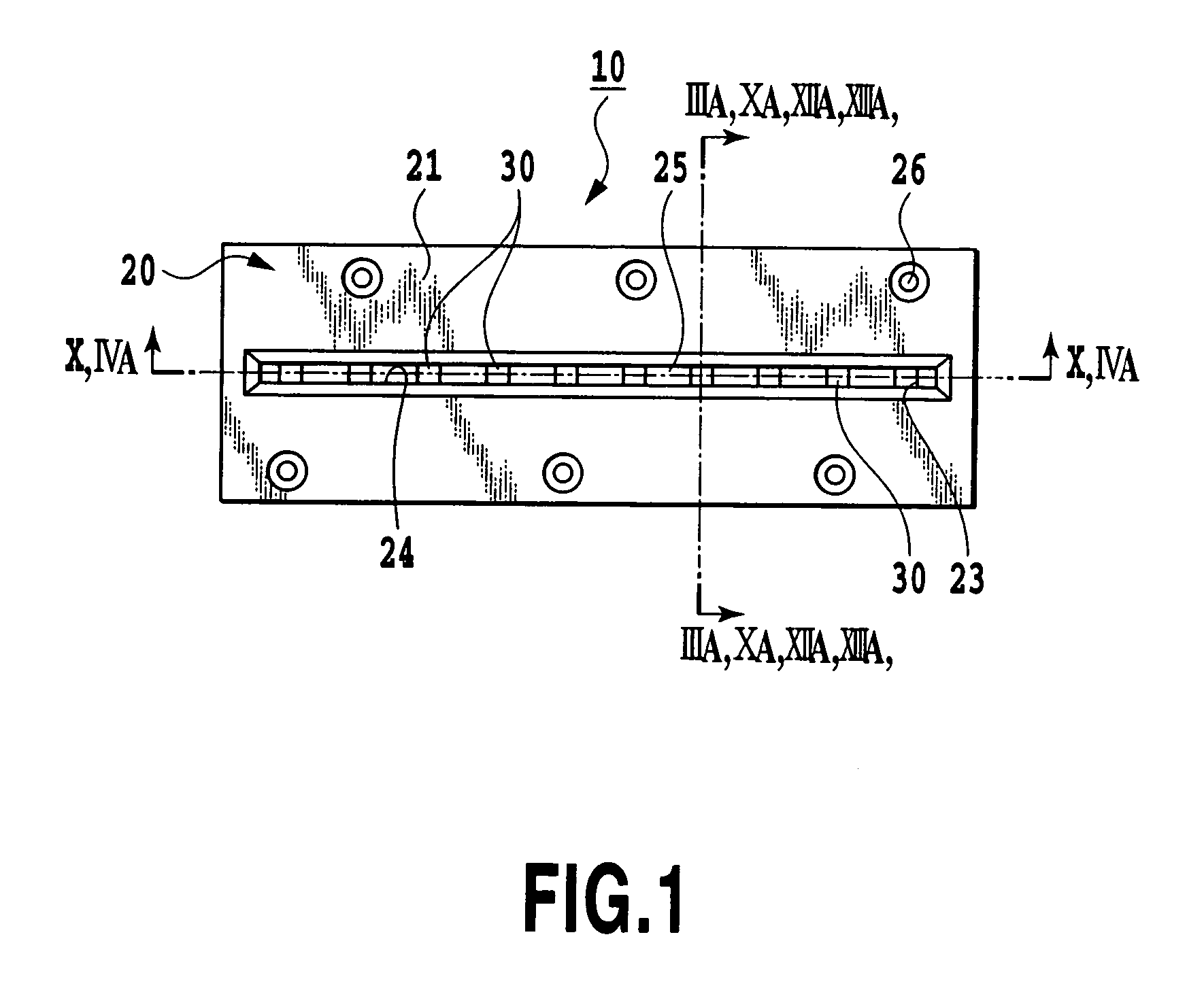
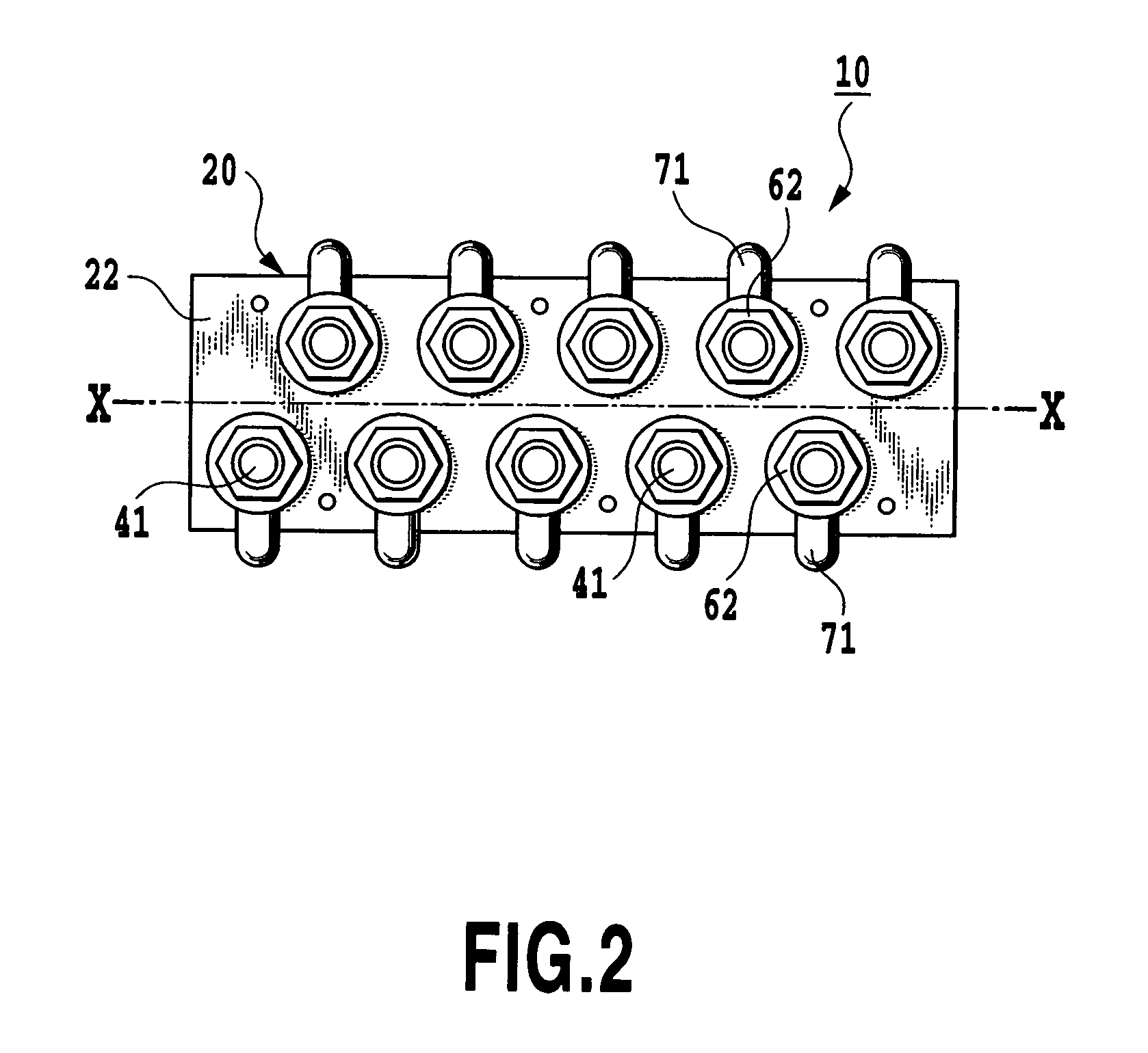
A female side connector for high current includes at least one contact unit including a contact, a contact support section, and a connection terminal: and a connector housing for placing the contact support section. The contact is provided by superposing a plurality of L-shaped and thin plate-like contact elements in the plate thickness direction, the contact element has a rectangular base end and a pair of elastically deformable arms that extend from the upper part of the rectangular base end and that respectively have opposing contact points at the neighborhood of the tip end. The contact support section supports the contact. The connection terminal is integrated with the contact support section and electrically contacts with outside. The contact is provided such that at least two or more contact elements having respectively different distances from the arm tip end to the contact point are superposed in the plate thickness direction.

Description

[0001]This application claims priority from Japanese Patent Application No. 2004-111540 filed Apr. 5, 2004, which is incorporated hereinto by reference.BACKGROUND OF THE INVENTION[0002]1. Field of the Invention[0003]The present invention relates to a female side connector for high current used for an operation such as an IC package test. More particularly, the present invention relates to a female side connector for high current to which or from which a conductor member or a card edge pad as a male side connector can be inserted or disengaged without requiring a large force.[0004]2. Description of the Related Art[0005]In a reliability test for an IC package or the like, a number of sockets respectively mounting thereon a number of IC packages are provided on a test board to be subjected to the test. For example, as shown in FIG. 19, in order to connect a burn-in test board, on which a number of sockets respectively sockets mounting thereon a number of IC packages (not shown) are arr...

Claims


Application Information

Patent Timeline
Patent Type & Authority Patents(United States)
IPC IPC(8): H01R24/00H01R4/30H01R11/12H01R13/11H01R13/115H01R13/187H01R13/193H01R13/40H01R33/76
CPCH01R13/112H01R12/88H01R13/193H01R13/113H01R4/30H01R11/12H01R12/721
Inventor SUZUKI, KATSUMINAKAMURA, YUJIICHIHARA, KENJI
Owner YAMAICHI ELECTRONICS
Learn More