
Industrial machine

a technology of industrial machines and guide parts, applied in the field of industrial machines, can solve problems such as errors, bent guide parts of base, deformation, etc., and achieve the effect of high accuracy and easy deformation of guide parts

Active Publication Date: 2019-05-14
MITUTOYO CORP
View PDF11 Cites 0 Cited by
  • Summary
  • Abstract
  • Description
  • Claims
  • Application Information

AI Technical Summary

Benefits of technology

[0005]This invention focuses on these points, and an object of the invention is to easily and with high accuracy obtain the amount of deformation of the guide part due to a load of a workpiece.

Problems solved by technology

For example, due to a load of the workpiece, the guide part of the base may be bent and deformed.
In such a case, because the movable body moves on the bent guide part, an error occurs in the result of the measurement of the workpiece by the probe supported by the movable body.

Method used


Image

  • Industrial machine
  • Industrial machine
  • Industrial machine

Examples


modification examples

[0060]Hereinafter, modification examples of the above-described coordinate measurement machine 1 are described with reference to FIGS. 7 to 9.

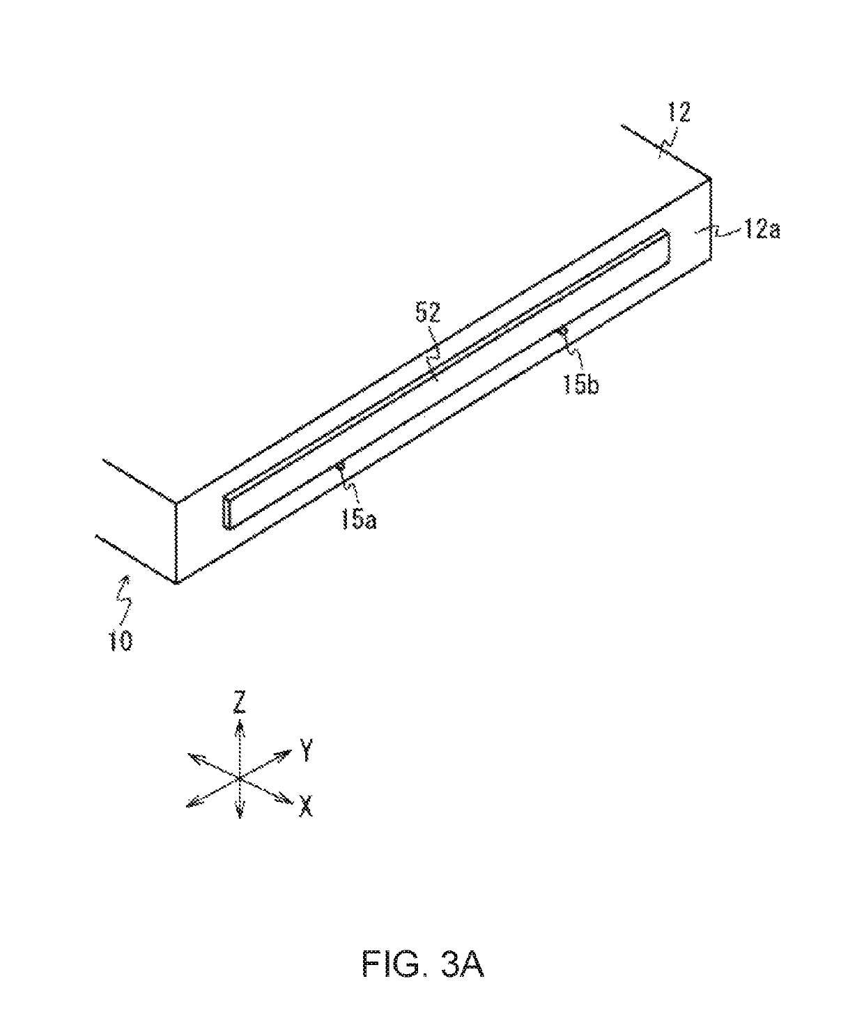
[0061]FIG. 7 is a diagram for describing a configuration according to a first modification example. In the above description, the scale 52 is supported by the support parts 15a and 15b (see FIG. 3A), but in the first modification example, the case member 70, to which the scale 52 is fixed, is supported by the support parts 15a and 15b as shown in FIG. 7.

[0062]The case member 70 is point-supported by the support parts 15a and 15b so that the case member 70 can be displaced in the Z-axis direction in a state where the case member 70 is parallel to the Y-axis direction. As a result, similarly to the above-described exemplary embodiment, the amount of displacement of the column 22 can be appropriately acquired. In addition, the case member 70 has a block shape. The case member 70 is made of a material having high rigidity and small thermal deforma...


PUM


Abstract

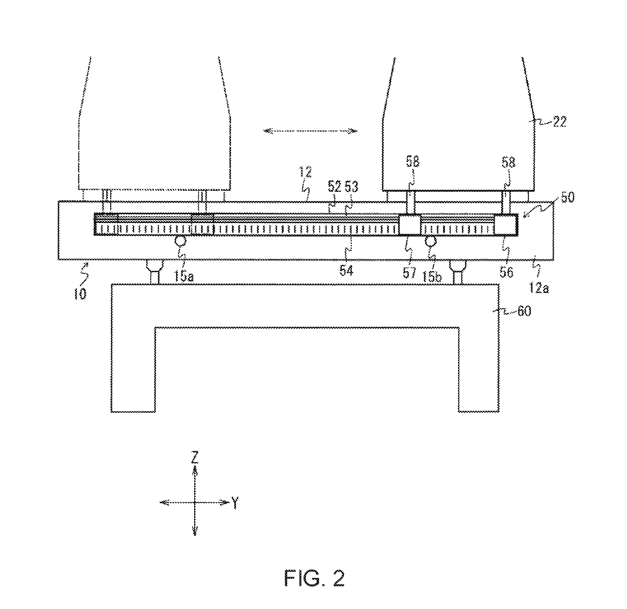
A coordinate measurement machine includes a column that can move relative to a placement surface on which a workpiece is placed, a guide part that is provided on the placement surface, the guide part guiding the column, a scale of a linear encoder that is supported on a side surface of the guide part, and detectors that are provided on the column, the detectors detecting a relative displacement with respect to the scale. The detectors detect a displacement of the column in each of a moving direction and a vertical direction. A coordinate measurement machine further includes a deformation amount acquisition part that acquires an amount of deformation of the guide part relative to the scale on the basis of detection results of the detectors.

Description

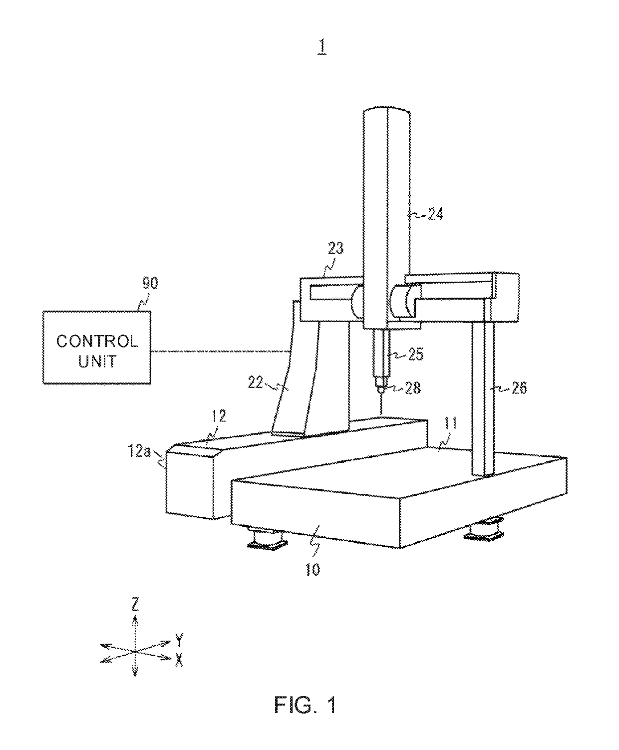
CROSS-REFERENCE TO RELATED APPLICATIONS[0001]The present application claims priority to Japanese Patent Application number 2016-119797, filed on Jun. 16, 2016. The content of this application is incorporated herein by reference in its entirety.BACKGROUND OF THE INVENTION[0002]The present invention relates to an industrial machine.[0003]As an industrial machine, for example, a coordinate measurement machine, which moves in orthogonal three-axis directions to measure coordinates and the like of a workpiece (an object to be measured), is used. In the coordinate measurement machine, the workpiece is measured by a probe while a movable body, which supports the probe, moves along a guide part of a base in a state where the workpiece is placed on a placement surface of the base.[0004]The base may be deformed when the workpiece is placed on the placement surface. For example, due to a load of the workpiece, the guide part of the base may be bent and deformed. In such a case, because the mov...

Claims


Application Information

Patent Timeline
Patent Type & Authority Patents(United States)
IPC IPC(8): G01B5/008G01B11/16G01B5/00
CPCG01B5/008G01B11/16G01B5/0004G01B5/30G01B21/045G01B5/0016
Inventor OTSUBO, SEIICHI
Owner MITUTOYO CORP
Learn More