Intake air quantity control device for internal combustion engine
a technology of quantity control device and intake air, which is applied in the direction of engine controller, machine/engine, mechanical apparatus, etc., to achieve the effect of improving the arrangement accuracy and facilitating and accurately arranging the quantity control devi
- Summary
- Abstract
- Description
- Claims
- Application Information
AI Technical Summary
Benefits of technology
Problems solved by technology
Method used
Image
Examples
embodiment 1
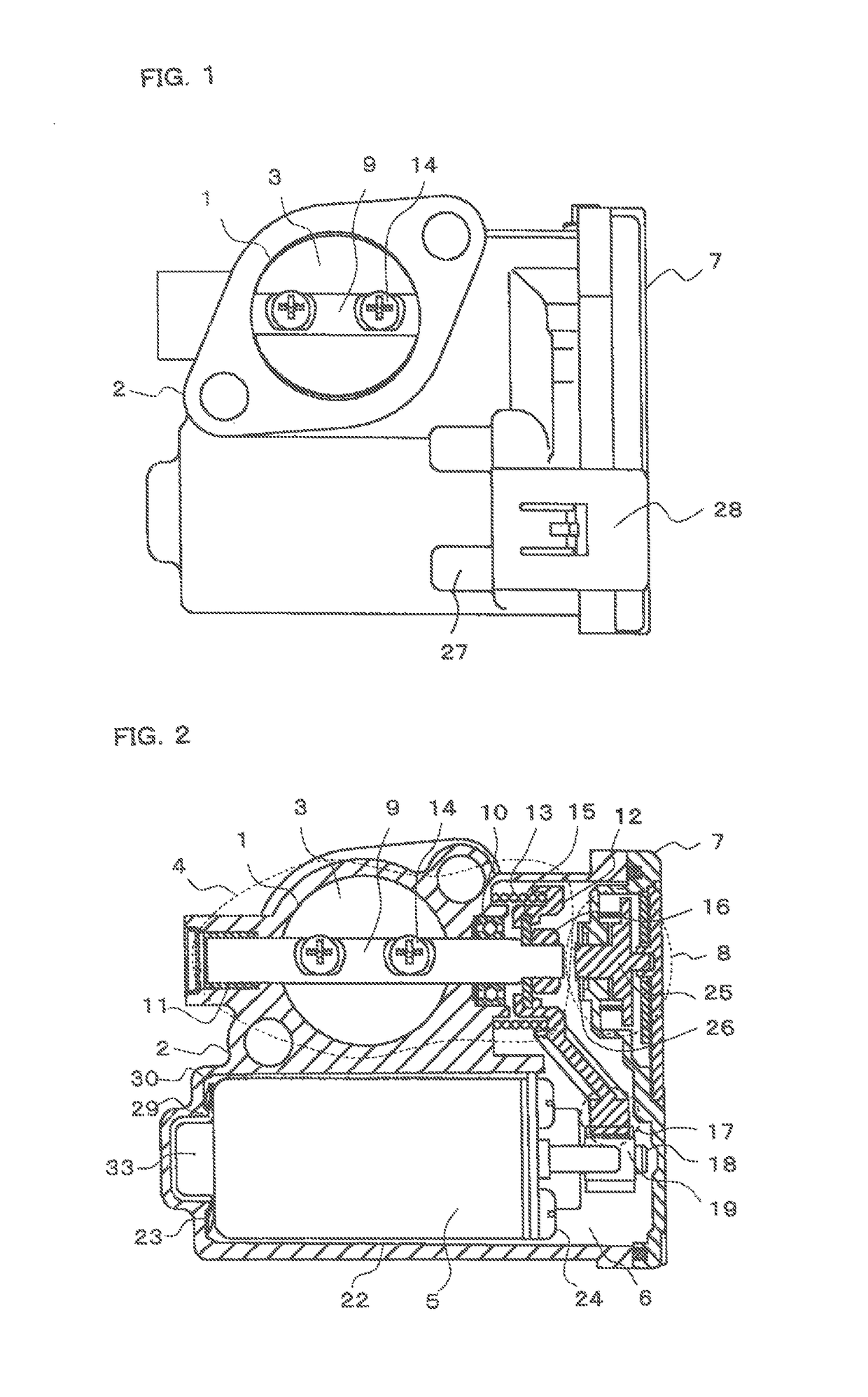
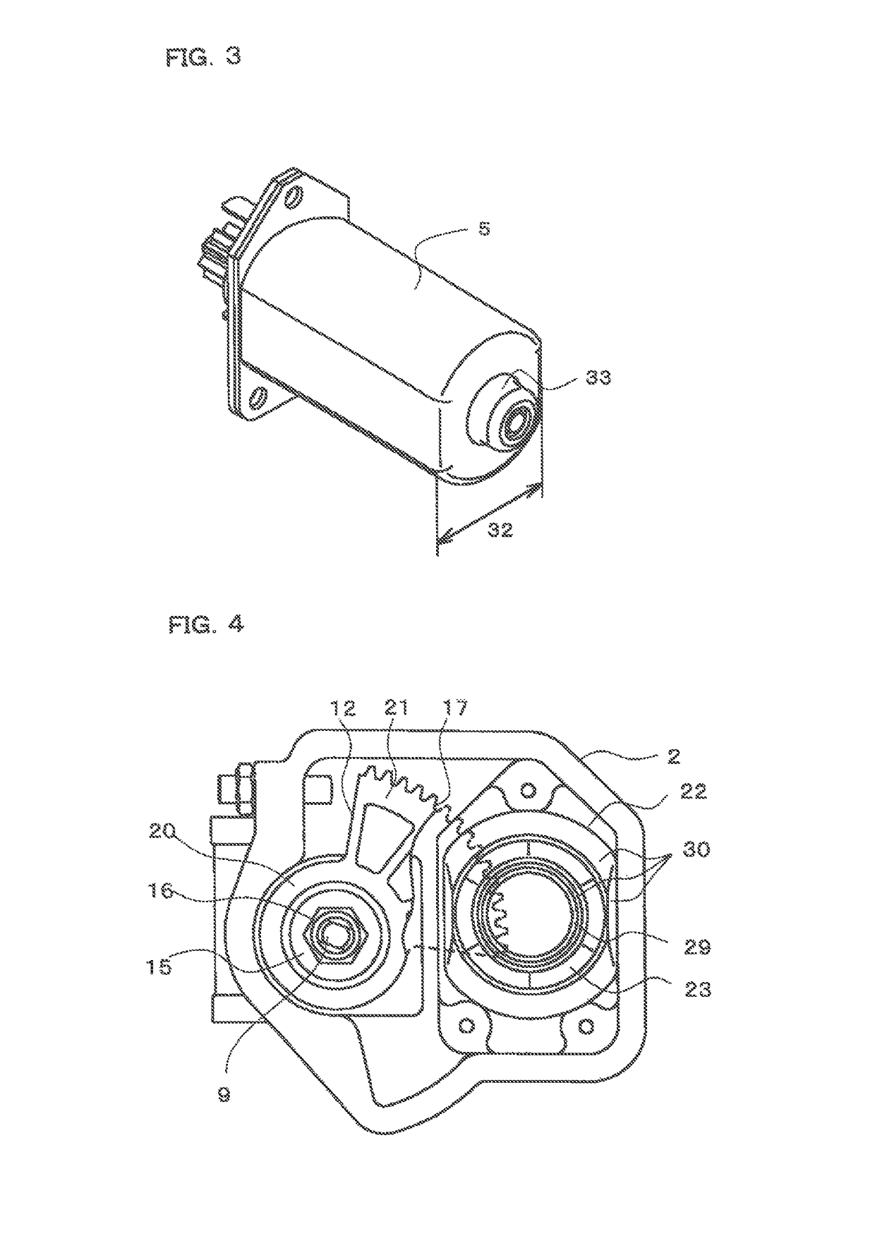
[0021]FIG. 1 is a front view illustrating an intake air quantity control device for an internal combustion engine according to Embodiment 1 of the present invention; FIG. 2 is a front cross-sectional view illustrating the intake air quantity control device for the internal combustion engine according to Embodiment 1 of the present invention; FIG. 3 is an explanatory view illustrating a drive motor in the intake air quantity control device for the internal combustion engine according to Embodiment 1 of the present invention; FIG. 4 is an explanatory view illustrating the intake air quantity control device for the internal combustion engine, in a state where a cover and the drive motor of the intake air quantity control device are dismounted, according to Embodiment 1 of the present invention; and FIG. 5 is a cross-sectional view illustrating a part of the intake air quantity control device for the internal combustion engine according to Embodiment 1 of the present invention. In FIG. ...
embodiment 2
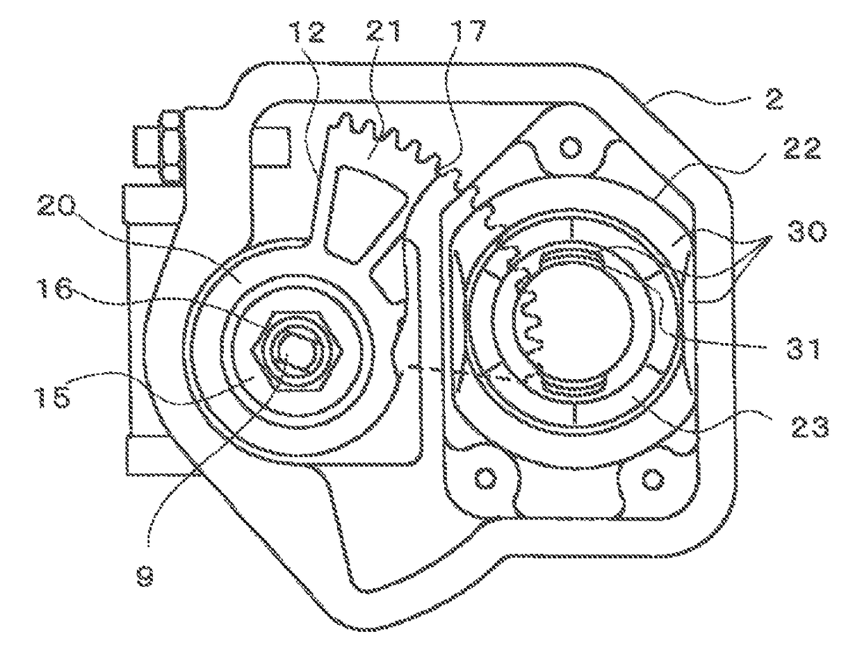
[0039]FIG. 6 is an explanatory view illustrating an intake air quantity control device for an internal combustion engine, in a state where a cover and a drive motor of the intake air quantity control device are dismounted, according to Embodiment 2 of the present invention. In FIG. 6, although a convex portion, which regulates a position of a wave washer 23, is provided on a bottom surface of a cylinder-shaped hole 22 of a throttle body 2 in a similar way as described in Embodiment 1, the convex portion is different from the ring-shaped convex portion 29 described in Embodiment 1, and half-moon-shaped convex portions 31, which are formed along a partial portion of a virtual ring having an outer diameter being smaller than an inner diameter of the wave washer 23, are arranged at two positions, which are faced each other, intervening a center of the cylinder-shaped hole 22. In addition, the convex portions 31 may be arranged at more than two positions. The convex portions 31 are forme...
embodiment 3
[0041]FIG. 7 is an explanatory view illustrating an intake air quantity control device for an internal combustion engine, in a state where a cover and a drive motor of the intake air quantity control device are dismounted, according to Embodiment 3 of the present invention. In FIG. 7, although two convex portions 31, which regulate a position of a wave washer 23 used in a similar way described in Embodiment 2, are provided on a bottom surface of a cylinder-shaped hole 22 of a throttle body 2, half-moon-shaped convex portions 31, which are formed along a partial portion of a virtual ring having an inner diameter being larger than an outer diameter of the wave washer 23, are arranged at two positions in a case of Embodiment 3, which are faced each other, intervening a center of the cylinder-shaped hole 22. When an inner diameter of the wave washer 23 is small in accordance with a specification of the wave washer 23, or when an outer diameter of a rear-end convex portion 33 of a drive ...
PUM
 Abstract
Description
Claims
Application Information
 - R&D
- Intellectual Property
- Life Sciences
- Materials
- Tech Scout
- Unparalleled Data Quality
- Higher Quality Content
- 60% Fewer Hallucinations
Browse by: Latest US Patents, China's latest patents, Technical Efficacy Thesaurus, Application Domain, Technology Topic, Popular Technical Reports.
© 2025 PatSnap. All rights reserved.Legal|Privacy policy|Modern Slavery Act Transparency Statement|Sitemap|About US| Contact US: help@patsnap.com


