Implant for bone fixation

a technology for implants and bone, applied in the field of bone fixation, can solve the problems of affecting the patient's health and even life, the time required for this opening procedure may be critical, and the patient may be unable to meet the requirements of the procedur

Active Publication Date: 2019-05-21
STRYKER EURO OPERATIONS HLDG LLC
View PDF28 Cites 3 Cited by
  • Summary
  • Abstract
  • Description
  • Claims
  • Application Information

AI Technical Summary

Problems solved by technology

The time required for this opening procedure may be critical for the patient's health and even life.
Similar or related problems occur in connection with other surgical procedure in which two or more bone parts need to be fixed.

Method used


Image

  • Implant for bone fixation
  • Implant for bone fixation
  • Implant for bone fixation

Examples


Embodiment Construction

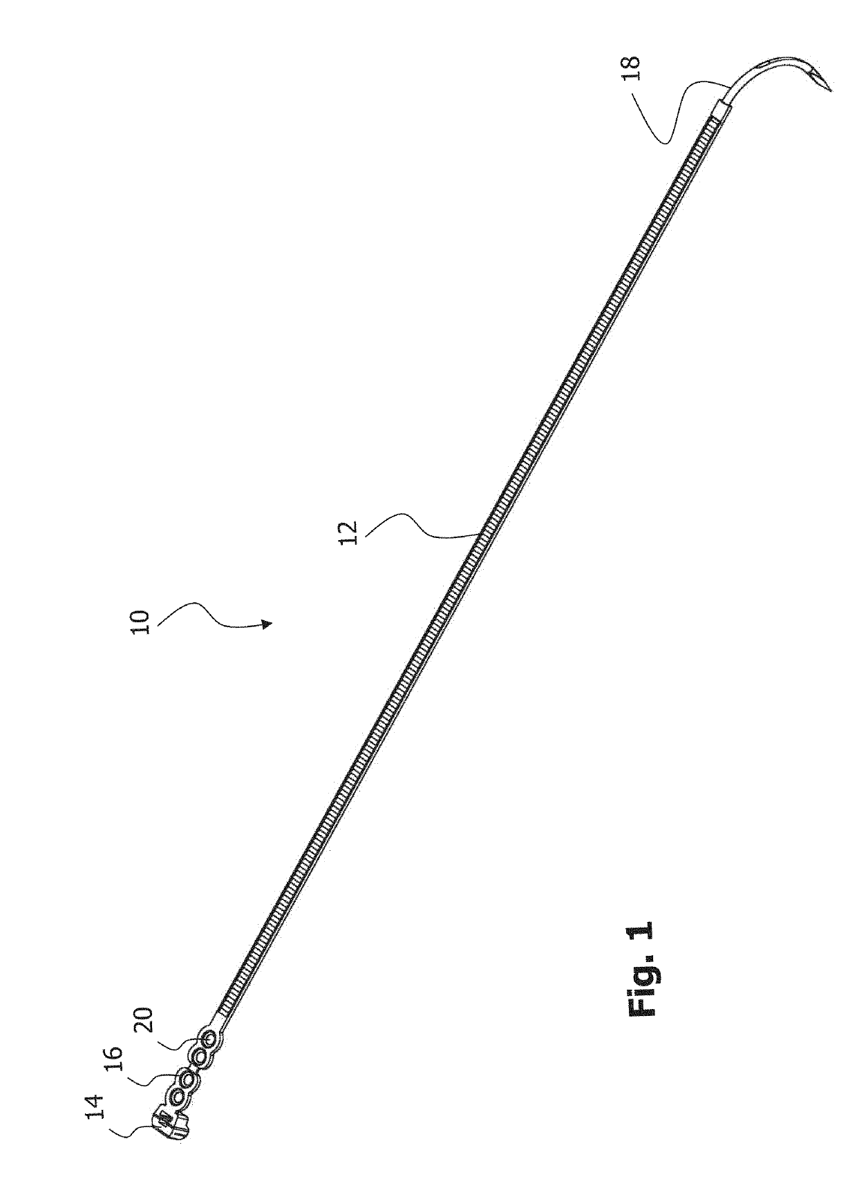
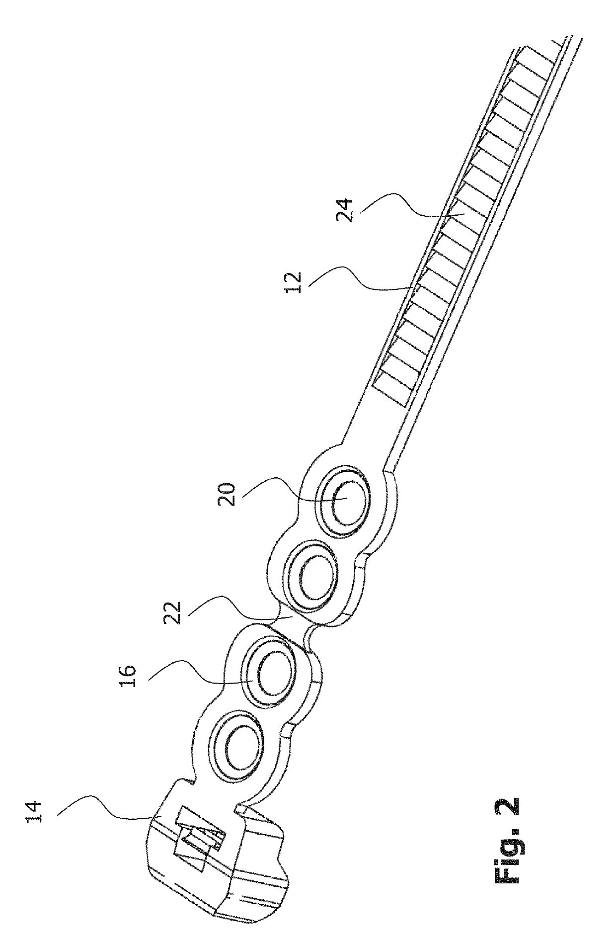
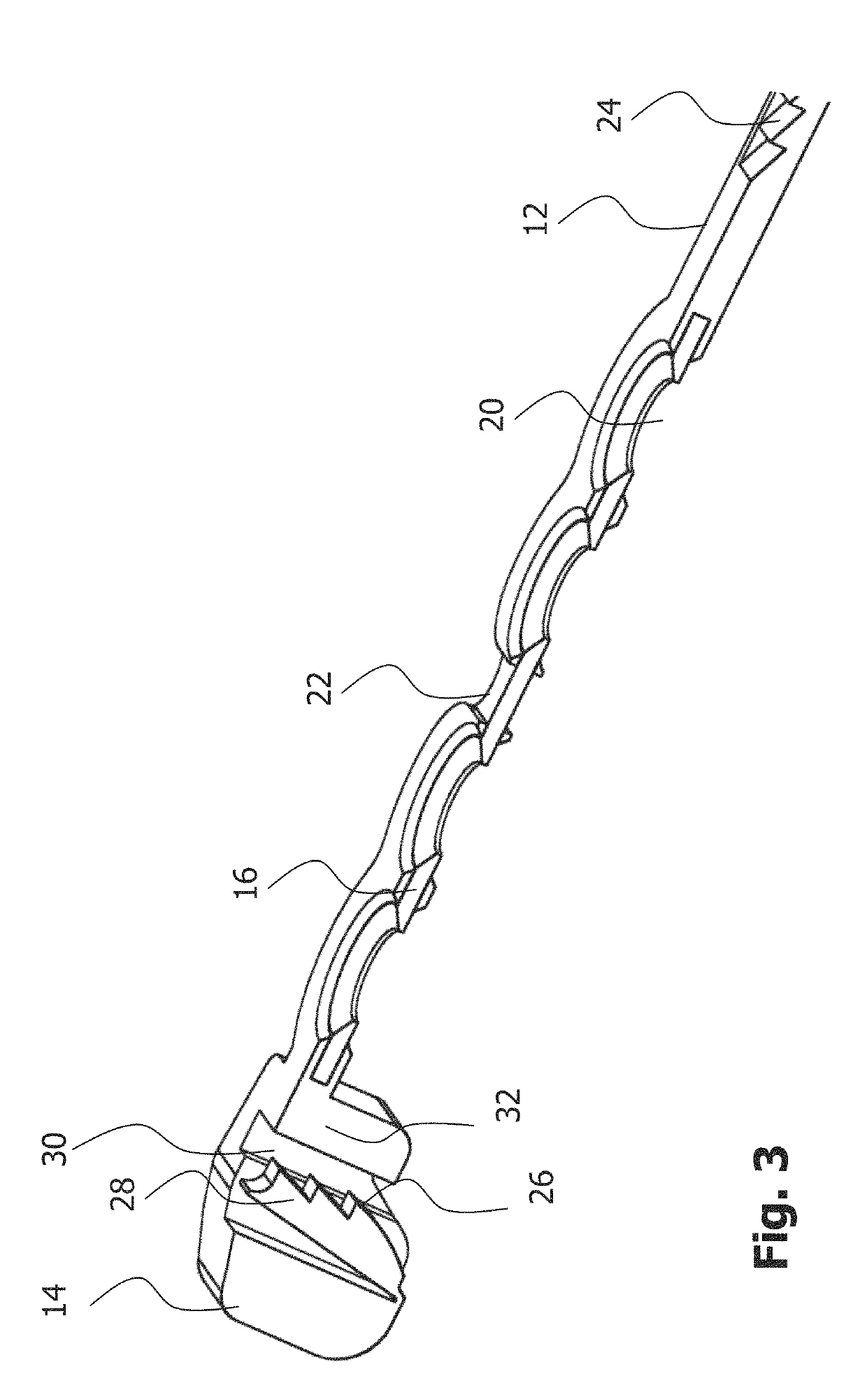
[0044]In the following description, exemplary embodiments of a bone fixation implant and an implant system comprising the implant and a bone fastener will be explained with reference to the drawings. The same reference numerals will be used to denote the same or similar structural features.

[0045]FIG. 1 shows a perspective view of an embodiment of a bone fixation implant 10. In the embodiment shown in FIG. 1, the implant 10 is configured and dimensioned for fixing bone parts of a sternum. It will be appreciated that the present disclosure is not limited to this surgical indication. Rather, the present disclosure can also be applied in connection with fixing bone parts in other regions of the human anatomy, possibly with suitably adapted configurations and dimensions.

[0046]The implant 10 shown in FIG. 1 comprises an elongated member 12, an engagement member 14 coupled to the elongated member 12, and a fastening member 16 arranged between and coupled to the elongated member 12 and the ...


PUM

PropertyMeasurementUnit
widthaaaaaaaaaa
angleaaaaaaaaaa
angleaaaaaaaaaa

Abstract

An implant for bone fixation is presented. The implant comprises an elongated member configured to be wound around bone parts that are to be fixed. Further, an engagement feature is provided that is coupled to the elongated member and configured to engage a portion of the elongated member so as to secure the implant in a loop around the bone parts. A fastening member is arranged between and coupled to the elongated member and the engagement member. The fastening member comprises at least one opening for receiving a bone fastener. In one variant, at least one visual indicator indicating a region of the fastening member to be severed in order to detach the implant is provided. In another variant, at least one of the engagement member and the elongated member are coupled to the fastening member by injection molding.

Description

CROSS-REFERENCE TO RELATED APPLICATION[0001]The present application claims priority from European Patent Application No. 15 000 033.9 filed Jan. 9, 2015 the disclosure of which is hereby incorporated herein by reference.TECHNICAL FIELD[0002]The present disclosure generally relates to bone fixation. Specifically, the disclosure relates to an implant for fixing bone parts, to systems comprising the implant, and to methods of manufacturing the implant.BACKGROUND OF THE INVENTION[0003]Various surgical procedures require the surgeon to access the thoracic region of a patient. A known approach to access the thoracic region is to cut the sternum in two parts and separate these two parts from each other for gaining access to the thoracic region. After completion of the surgical procedure, the separated parts of the sternum are brought back to their initial positions and fixed, for example, with a bone plate attached to the sternum parts or a wire tensioned around the circumference of the st...

Claims


Application Information

Patent Timeline
Patent Type & Authority Patents(United States)
IPC IPC(8): A61B17/82A61B17/86A61B17/80A61B17/00A61B90/00
CPCA61B17/82A61B17/8076A61B17/823A61B17/8052A61B2090/037A61B17/86A61B2017/00407A61B2017/00526A61B2017/00955A61B17/8085B29C45/14336B29L2031/7532
Inventor KNOEPFLE, CHRISTIANGREINER, KARLSCHMUCK, MANFRED
Owner STRYKER EURO OPERATIONS HLDG LLC
Why Eureka
Try Eureka