Image projection apparatus and operation method thereof

a technology of image projection apparatus and operating method, which is applied in the direction of picture reproducers using projection devices, television systems, instruments, etc., can solve the problems of image projection apparatus not receiving user input through touch, limiting the size of the screen on which the image is displayed, and reducing the use of space. , to achieve the effect of improving the outer appearance, improving the user's viewing environment, and increasing the utilization of spa

Active Publication Date: 2019-06-04
LG ELECTRONICS INC
View PDF10 Cites 0 Cited by
  • Summary
  • Abstract
  • Description
  • Claims
  • Application Information

AI Technical Summary

Benefits of technology

[0017]According to various embodiments of the present invention, the image projection apparatus according to the present invention may project the image to various positions, thereby increasing the utilization of a space and improving an outer appearance.
[0018]In addition, according to the present invention, the state of an image projection area, to which an image is projected, may be determined, and the image corresponding to the determined image projection area may be projected, thereby providing a pleasant viewing environment for the user.
[0019]In addition, according to the present invention, the user input to the projected image may be recognized so that the operation and the function desired by the user may be easily performed.

Problems solved by technology

According to the displaying of the image through the display device, there are a limitation in the size of a screen on which the image is displayed and a difficulty in displaying the image on an area other than the screen of the display device.
However, the image projection apparatus may not receive the user input through the touch manner due to the feature that there is absent a specific display in the image projection apparatus.
In addition, if the user is directly exposed to the projected image, the eyesight of the user may be damaged.
The above disadvantages of the image projection apparatus may need to be solved.

Method used


Image

  • Image projection apparatus and operation method thereof
  • Image projection apparatus and operation method thereof
  • Image projection apparatus and operation method thereof

Examples


Embodiment Construction

[0056]Hereinafter, embodiments relating to the present invention will be described in detail with reference to the accompanying drawings. The suffixes “module” and “unit” for components used in the description below are assigned or mixed in consideration of easiness in writing the specification and do not have distinctive meanings or roles by themselves.

[0057]Hereinafter, an operating method of an image projection apparatus and the image projection apparatus using the same according to an embodiment of the present invention will be described in detail.

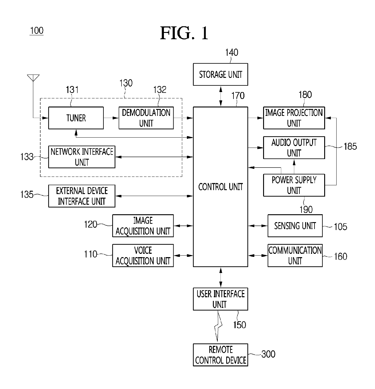
[0058]The image projection apparatus according to an embodiment of the present invention, which is, for example, an intelligent image projection apparatus in which a computer aid function is added to a broadcast reception function, may perform sufficiently the broadcast reception function while additionally performing the Internet function. Accordingly, the image projection apparatus may have an interface, such as voice command recogni...


PUM


Abstract

An image projection apparatus according to an embodiment of the present invention senses the distance to an image projection area to which an image is projected, and determines an image projection state including a state of at least one of the image projection area and a space between the image projection apparatus and the image projection area, on the basis of the sensed distance. The image projection apparatus projects an image onto the image projection area on the basis of the determined image projection state.

Description

CROSS-REFERENCE TO RELATED APPLICATIONS[0001]This application is the National Stage filing under 35 U.S.C. 371 of International Application No. PCT / KR2015 / 008366, filed on Aug. 10, 2015, and also claims the benefit of earlier filing date and right of priority to Korean Patent Application Nos. 10-2015-0071272, filed on May 21, 2015 and 10-2015-0017547, filed on Feb. 4, 2015, the contents of which are all hereby incorporated by reference herein in their entirety.TECHNICAL FIELD[0002]The present invention relates to an image projection apparatus and an operating method thereof, and more particularly to an image projection apparatus and an operating method thereof, capable of determining a state of an image projection area, to which an image is projected, and of performing an operation corresponding to the determined state of the image projection area.BACKGROUND ART[0003]Recently, a manner of displaying an image may include not only a manner of displaying an image inside a device simila...

Claims


Application Information

Patent Timeline
Patent Type & Authority Patents(United States)
IPC IPC(8): G06F3/01G06F3/0488G06F3/0484G06F3/0482G06F3/042H04N9/31H04N5/74G06F3/03
CPCG06F3/0425G06F3/017G06F3/0304G06F3/0482G06F3/04842H04N5/74H04N9/31H04N9/3179G06F3/0488G06F2203/04101H04N9/3182H04N9/3185H04N9/3188H04N9/3194
Inventor LEE, SANGHOKIM, KYOUNGJOUNGLEE, KYUNGHOYOU, HYUNHEEYOON, HYUNSIKKIM, YANGSIKLIM, JIHWANPARK, JEONGHOONKIM, TAESOONKANG, SANGKYU
Owner LG ELECTRONICS INC
Why Eureka
Try Eureka