Battery-powered percussive massage device with pressure sensor

a percussive massage and battery-powered technology, applied in the field of therapeutic devices, can solve the problems of tethered, unable to fully complete the treatment regime, and the manual force applied to the body varies,

Active Publication Date: 2019-06-11
HYPERICE IP SUBCO LLC
View PDF22 Cites 147 Cited by
  • Summary
  • Abstract
  • Description
  • Claims
  • Application Information

AI Technical Summary

Benefits of technology

[0008]Another aspect in accordance with embodiments disclosed herein is a battery-powered percussive massage device. The device includes an enclosure having a cylindrical bore. The cylindrical bore extends along a longitudinal axis. A piston is located within the cylindrical bore. The piston has a first end and a second end. The piston is constrained to move only along the longitudinal axis of the cylindrical bore. A motor is positioned within the enclosure. The motor has a rotatable shaft. The shaft has a central axis. The central axis of the shaft is perpendicular to the longitudinal axis of the cylindrical bore. A crank is coupled to the shaft. The crank includes a pivot, which is offset from the central axis of the shaft. A reciprocation linkage has a first end and a second end. The first end of the reciprocation linkage is coupled to the pivot of the crank. The second end

Problems solved by technology

Percussive massage may be applied by a skilled massage therapist using rapid hand movements; however, the manual force applied to the body varies, and the massage therapist may tire before completing a sufficient treatment regime.
Many of the known percussive applicators are expensive, large, relatively heavy, and tethered to an electrical power source.
Some percussive applicators are relatively noisy because of the conventional mechanisms used to convert

Method used


Image

  • Battery-powered percussive massage device with pressure sensor
  • Battery-powered percussive massage device with pressure sensor
  • Battery-powered percussive massage device with pressure sensor

Examples


Embodiment Construction

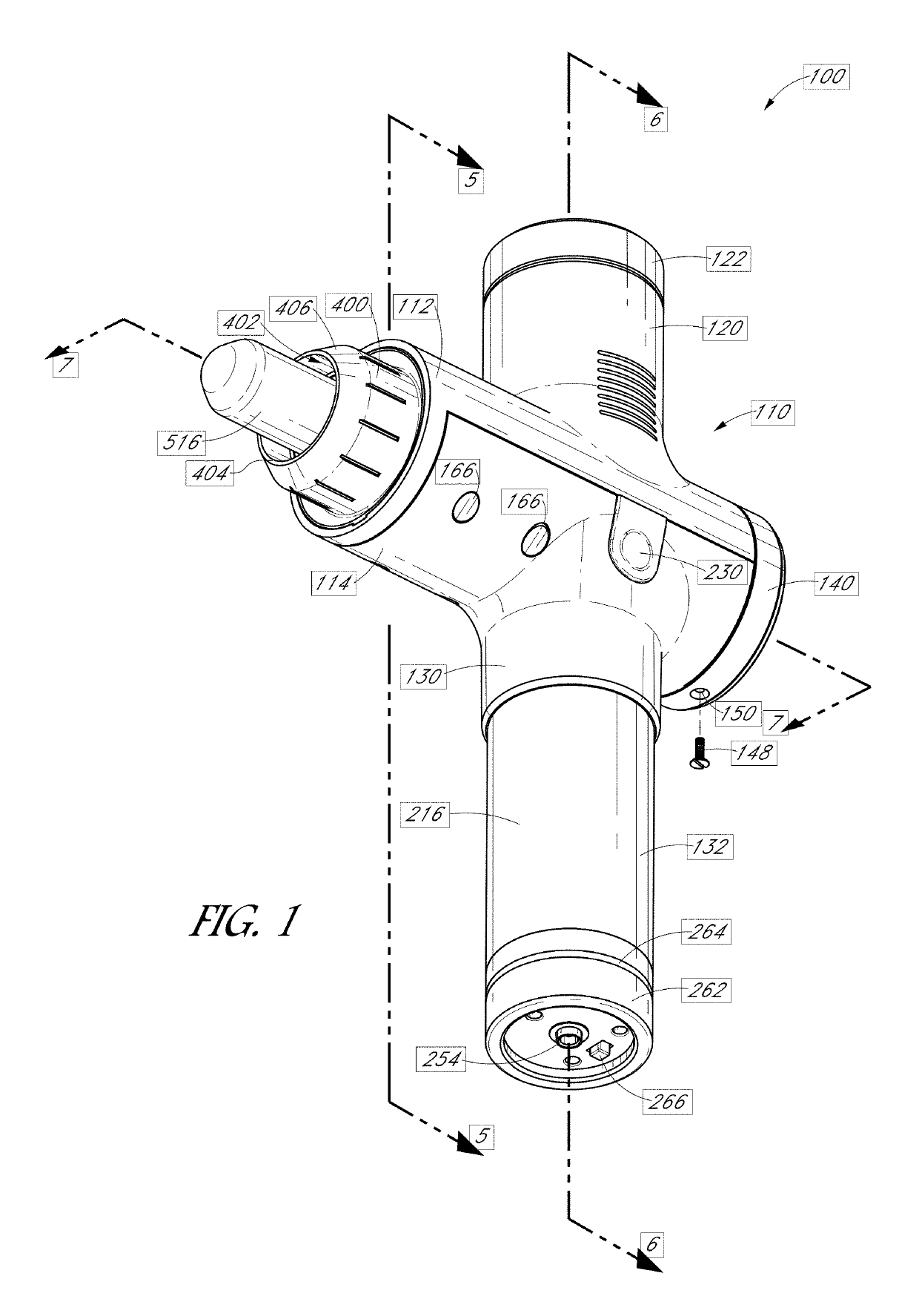
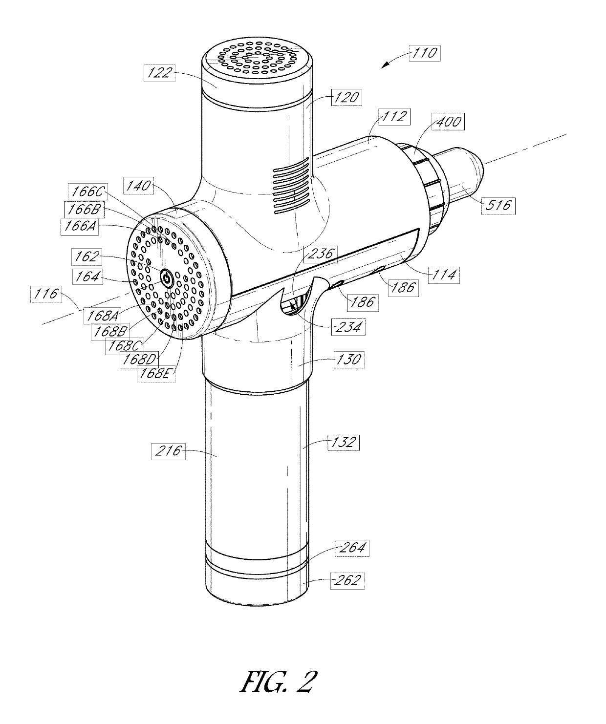
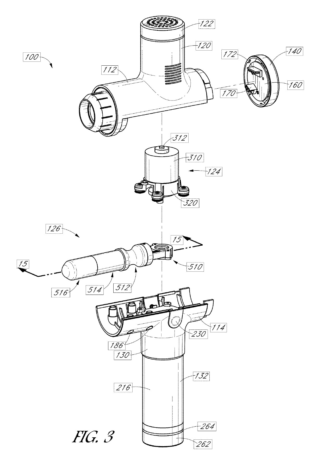
[0066]As used throughout this specification, the words “upper,”“lower,”“longitudinal,”“upward,”“downward,”“proximal,”“distal,” and other similar directional words are used with respect to the views being described. It should be understood that the percussive massage applicator described herein can be used in various orientations and is not limited to use in the orientations illustrated in the drawing figures.

[0067]A portable electromechanical percussive massage applicator (“percussive massage applicator”) 100 is illustrated in FIGS. 1-22. As described below, the percussive massage applicator can be applied to different locations of body to apply percussion to the body to effect percussive treatment. The percussive massage applicator is operable with removably attachable applicator heads to vary the effect of the percussive strokes. The percussive massage applicator operates at a plurality of speeds (e.g., three speeds).

[0068]The portable electromechanical percussive massage applicat...


PUM


Abstract

A percussive massage device includes an enclosure having a cylindrical bore that extends along a longitudinal axis. A motor has a rotatable shaft that rotates about a central axis perpendicular to the longitudinal axis. A crank coupled to the shaft includes a pivot, which is offset from the central axis of the shaft. A reciprocation linkage has a first end coupled to the pivot of the crank. A piston has a first end coupled to a second end of the reciprocation linkage. The piston is constrained to move within a cylinder along the longitudinal axis of the cylindrical bore. An applicator head has a first end coupled to a second end of the piston and has a second end exposed outside the cylindrical bore for application to a person receiving treatment. A motor controller measures current applied to the motor and displays a pressure indicator responsive to the measured current.

Description

RELATED APPLICATIONS[0001]This application claims the benefit of priority under 35 USC § 119(e) of U.S. Provisional Application No. 62 / 759,968 filed on Nov. 12, 2018; U.S. Provisional Application No. 62 / 760,617 filed on Nov. 13, 2018; and U.S. Provisional Application No. 62 / 767,260 filed on Nov. 14, 2018, which are incorporated herein by reference in their entireties.FIELD OF THE INVENTION[0002]The present invention is in the field of therapeutic devices, and, more particularly, is in the field of devices that apply percussive massage to selected portions of a body.BACKGROUND OF THE INVENTION[0003]Percussive massage, which is also referred to as tapotement, is the rapid, percussive tapping, slapping and cupping of an area of the human body. Percussive massage is used to more aggressively work and strengthen deep-tissue muscles. Percussive massage increases local blood circulation and can even help tone muscle areas. Percussive massage may be applied by a skilled massage therapist us...

Claims


Application Information

Patent Timeline
IPC IPC(8): A61H1/00A61H23/02A61H23/00
CPCA61H23/006A61H23/0254A61H23/004A61H1/008A61H2201/5043A61H2201/1436A61H2201/5071A61H2201/5097A61H2201/5058A61H2205/081A61H2201/0153A61H2201/0157A61H2201/5002A61H2201/5041A61H2201/501A61H2201/0188A61H2201/169A61H2201/1215A61H2201/1685
Inventor MARTON, ROBERTKATZ, ANTHONY
Owner HYPERICE IP SUBCO LLC
Why Eureka
Try Eureka